PCB Repair Logs Blood Brothers
Blood Brothers
 |
|
| Manufacturer | TAD Corporation |
|---|---|
| Year | 1990 |
| PCB Image | Reserved |
| Pin Out | Jamma Pinout |
Repairer: GameDude
Forum Thread: Blood Brothers PCB Repair
Another Ebay "works Perfect"
Anyway this one had no sound, checked the Z80 and clock / data was there looks like someone lifted the ROMS out of the socket (minor damage) so someone knew there was no sound at one stage.
Followed the data up through the OKI chip then on to the Yamaha sound all OK so far, Hmm check AMP, getting power OK, getting warm OK, touching the amp circuit with a finger produced no static. Probed further to the output no activity.
Used a multimeter to check continuity between the JAMMA connector and the AMP and noticed that one of the pins on the resistor packs things was never soldered from the factory could it be this simple?
YES! It looks like from the factory it worked but over the years tarnishing has reduced the pitiful contact to nothing, resoldered and audio came back. Still dont like Ebay for sellers testing properly. STATUS :- FIXED.
I would also like to mention this game is extremely fun, plenty to destroy in the background and very intense on hard. After I played Cabal this was a welcome game to see.
Repairer: Devil Soundwave
Forum Thread: Brothers PCB Repair
Got home this evening for the start of a long weekend (thank ****, I'm knackered!) and had a new baggy of components I'd ordered off eBay that arrived this morning, so I decided to tackle one of my many projects.
So, having perused the various harnesses/cables/autofire protos and other stuff I have on the go, I decided to ignore them all and instead attempt my first PCB repair!
I looked in my logbook to see what I fancied tackling, and chose a poorly copy of Blood Bros., the western based sequel to Cabal. I had it marked down as being a worker, but with some control issues on P1 and zero sound - seemed like an easy enough start!
30 minutes of swearing later, I had retrieved it from the cupboard of doom, and proceeded to fire up the board. A few minutes of playing the game and messing about with the volume pot confirmed that a) the sound was non-existent and b) player one UP was not working.
Task number one - fix the controls.
I had a close look at the board all over with a magnifying glass and was not sure what was going on as I couldn't see anything obvious. A tedious 20 mins later - I noticed a tiny scratch through the traces next to the JAMMA edge on the parts side, which proved to be the culprit when metred! Yay!
Whilst I *could* have scraped back the solder mask and used kynar to bridge the scratch; I decided it was a bit too ambitious for my first repair as the trace was very short and I've not got a very steady hand, so instead, I decided to wrap a wire round the board, through a spare screw hole to the back of the next component on the trace:
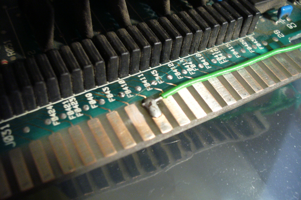
Note the scratch. It's weird that the cut appears deeper over other tracks but they were unaffected. Odd!
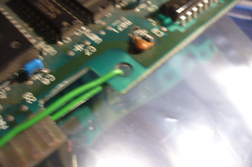
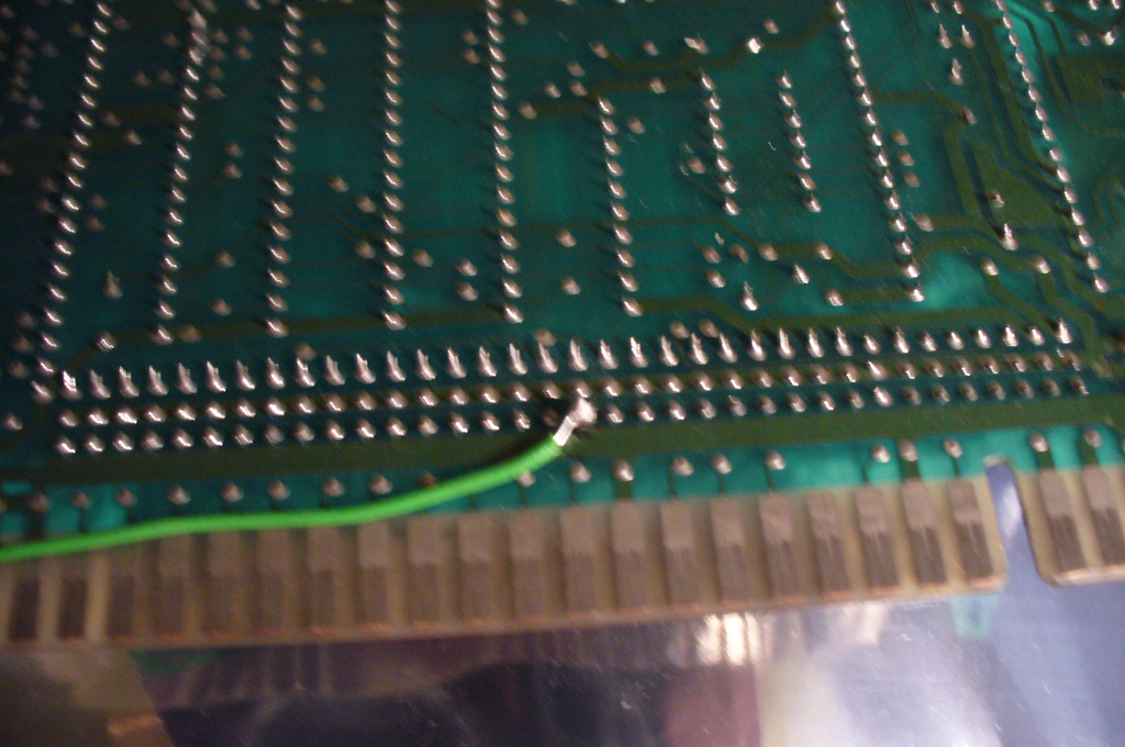
So, first attempt in - I decide to test and see.
Fire it up and start a game, and reticule is in the middle of the screen:
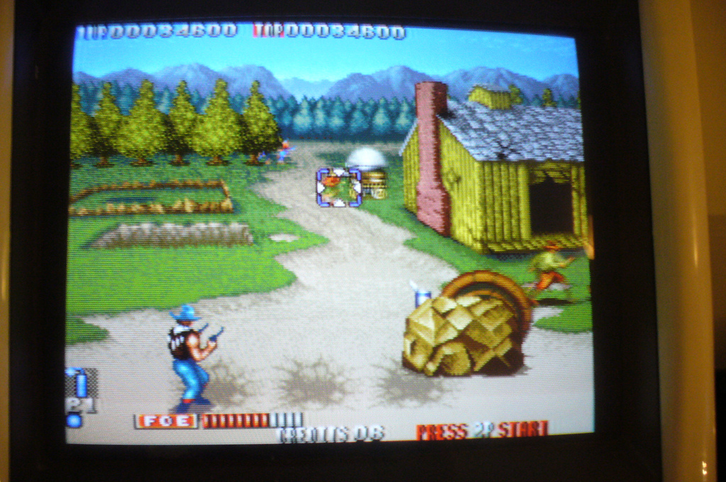
Take a breath and push up and... SUCCESS!
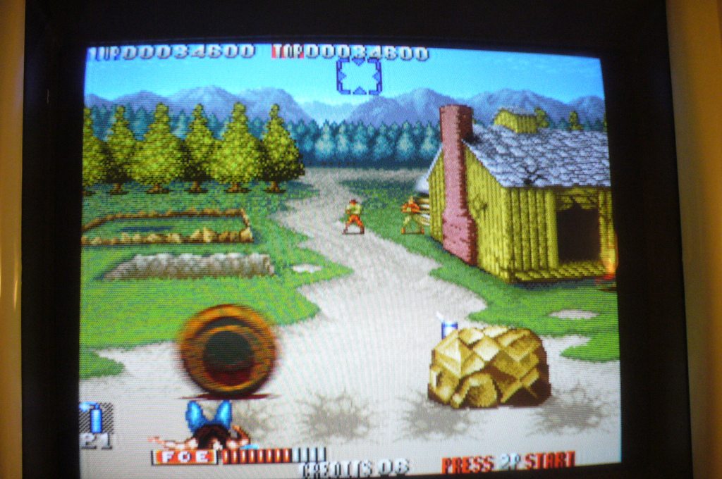
Bouyed by my mini-win, I moved onto the sound. Looking at the soundstage, the culprits seemed pretty bloody obvious:
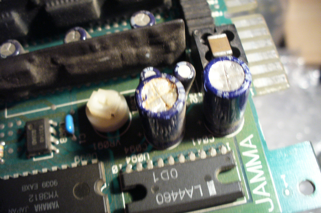
Two 1000uf 16v caps, both battered, one appearing leaky.
Now here's the interesting bit - on turning it over to desolder the caps - I find that they appear to have been messed with by someone before judging by the surface scratching and the amount of solder on each point:
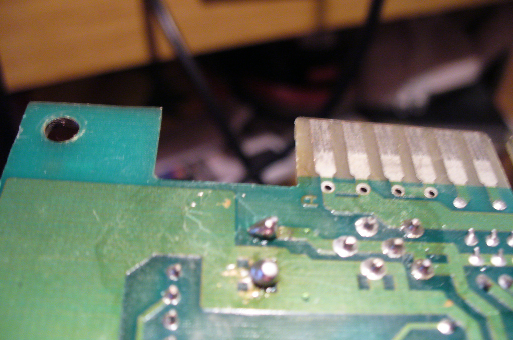
Disappointingly, when i had removed the caps, I wasn't pleased with what I saw. The board traces around two of the vias had been pretty much ruined by the previous owners botch-job. :|
I soldered a new cap in the good spot. Admittedly it looks messy, but tbh the vias on that one where a bit borked also, but luckily there was just enough to solder to. You can see the two traceless vias below it:
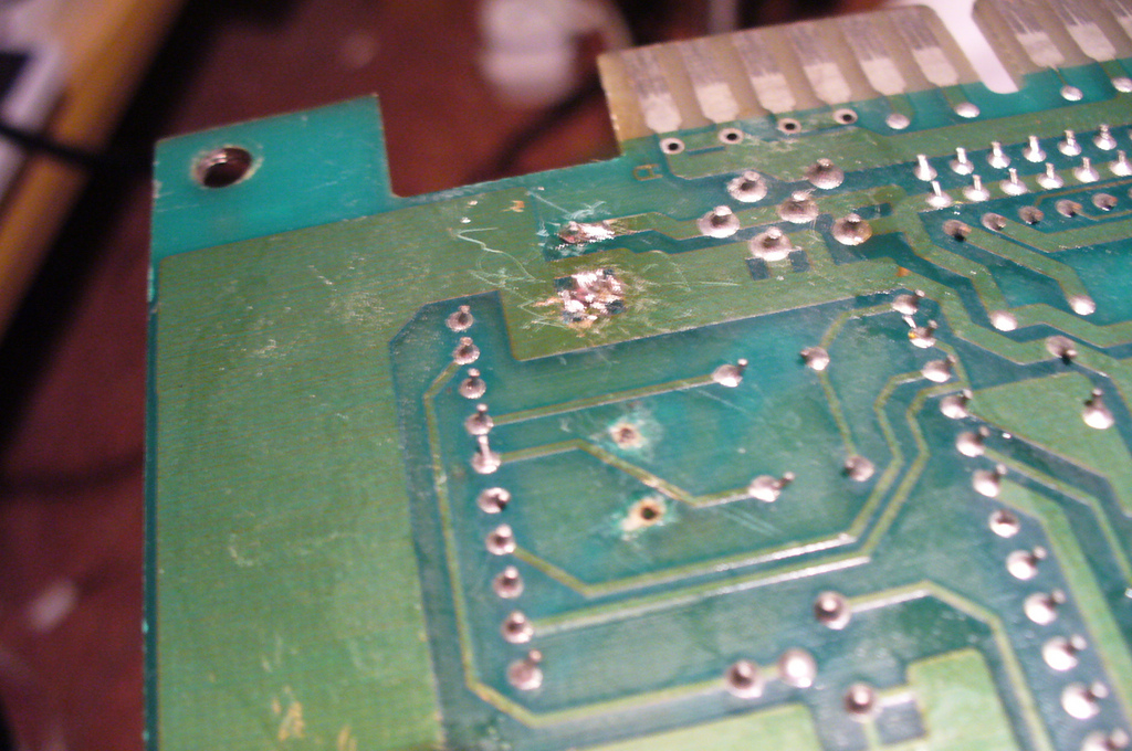
At this point, I was about ready to give up, so I decided a break was in order. I had a cup of tea and tried to decide how to go about dealing with the screwed vias.
In the end, I decided I'd just have to scrape back some solder mask for the negative pin:
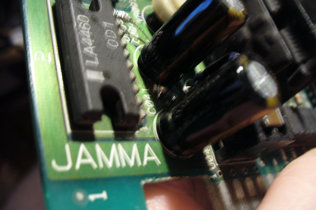
And solder the positive pin directly to the next component in the circuit:
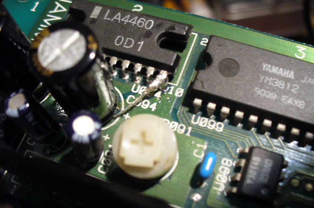
So - had it done the trick? I fired it up and... SOUND! :awe:
Finally, I put a couple of blobs of hot glue next to the "surface mounted" cap to give it stability.
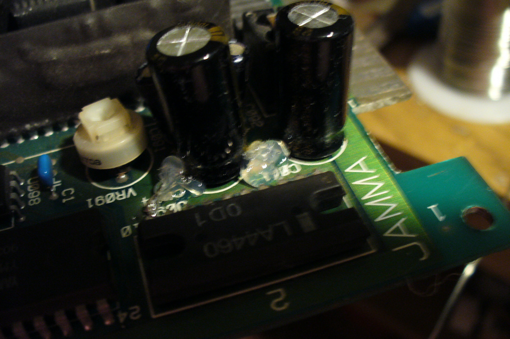
Pretty simple I know, but I'm feeling very pleased with myself.