PCB Repair Logs Strikers 1945
Strikers 1945
 |
|
| Manufacturer | Psikyo |
|---|---|
| Year | 1995 |
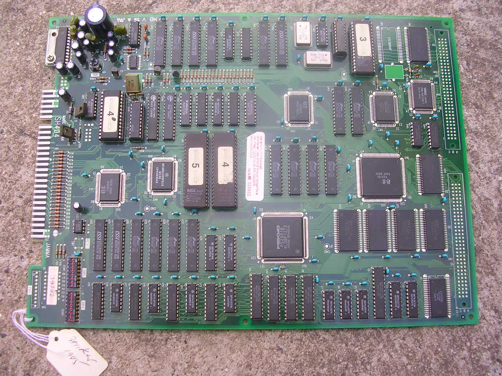
| PCB Image | Strikers 1945 PCB |
| Pin Out | Jamma |
Repairer: Womble
Forum Thread: Strikers 1945 PCB Repair
Picked up a fault Psycho Strikers 1945 PCB recently..

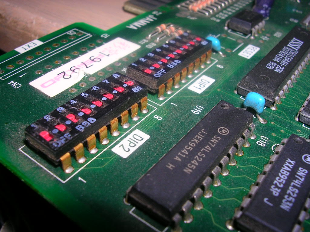
..was sold as having no sound. The PCB itself was in pristine condition, hardly a mark on it and looked very well made, never seen gold plated dip switch DIPs before.

“No sound” wasn’t really the case, it had sound but it sounded like a kettle boiling, randomly dropping into periods of very rough white noise.
The fact it was making an unholy noise proved the amplifier chip was working, although was getting stinking hot, and the volume pot did what it was supposed to do. Overheating amp chips are often a sign that the chip is oscillating cause by noise on the 12V rail, this is usually overcome with a couple of capacitors between the 12V rail and ground, often a large electrolytic of thousands mircofarads, and a very small polyester cap in the nanofarad range, between them they mop up the noise on the rails coming from the PSU. On this board both caps were where they should be and the electro had a healthy ESR rating. The other potential cause was the audio signal itself that was upsetting the chip and causing it to oscillate, and judging by the sound of it this seemed plausible.
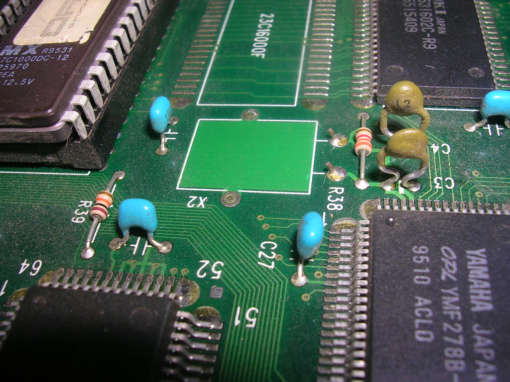
With the amp section almost ruled out I moved onto the audio generation area of the board, on most boards this is close to the amp but on this board it was right at the back of the board. There are two ways to approach sound faults, either start with the DACs and work back from its input, or start at the audio CPU, check it is enabled and then work out. Everything was surface mount which is often makings things more difficult but before I got round to getting the scope warmed up I found the fault. The crystal resonator was missing, it had snapped off so neatly that it wasn’t clear there had been anything there without looking very closely

The other crystals on the board were installed so they were poking up and easily knocked off.
Finding out what frequency the crystal should have been was the next issue, the silkscreening on the board didn’t say and according to MAME there are three variants of this board, all with different audio sections. This board is the one with a Yamaha YMF278B which apparently should be driven at 33.8688Mhz, however on PCBs the speed a chip is driven often doesn’t exactly translate to the frequency of the clock crystal. This is because the signal from the crystal is not exactly clean, so it gets fed into some logic to divide it down, the end result is a far cleaner signal than you would get if you had a crystal of the exact speed. In this case the crystal connects straight between two pins on the YMF278B, the YMF datasheet showed it needed this exact speed which is divided down internally to the common audio frequencies.
Tracking down a new one would cost me $18 plus postage within Australia, so I ended up buying 20 for a grand total of $5 including postage from Hong Kong.
Once fitted on the board the fault vanished, full audio was restored and the amp chip now runs slightly warm.
Job done.