Difference between revisions of "PCB Repair Logs Golden Axe"
m |
m |
||
| Line 15: | Line 15: | ||
</table></p> | </table></p> | ||
__TOC__ | |||
===Board 1=== | ===Board 1=== | ||
Revision as of 07:25, 29 August 2012
Golden Axe
 |
|
| PCB Image | Golden Axe |
|---|---|
| Pin Out | Reserved |
Board 1
Repairer: Womble
Forum Thread: Golden Axe PCB Repair
Got hold of a box of faulty boards lately, was expecting 2 boards but got 3, the third was a rather battered and sad looking Golden Axe.
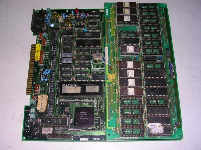
Didn't hold out much hope for it as it had a number of signs of a hard life. Most obviously was a couple of ridiculously long wires soldered to the underside to repair damage.
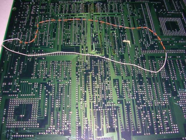
The underside of the board was peppered with scratch marks..
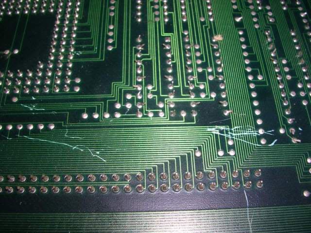
...and one corner of the main board had been snapped clean off.
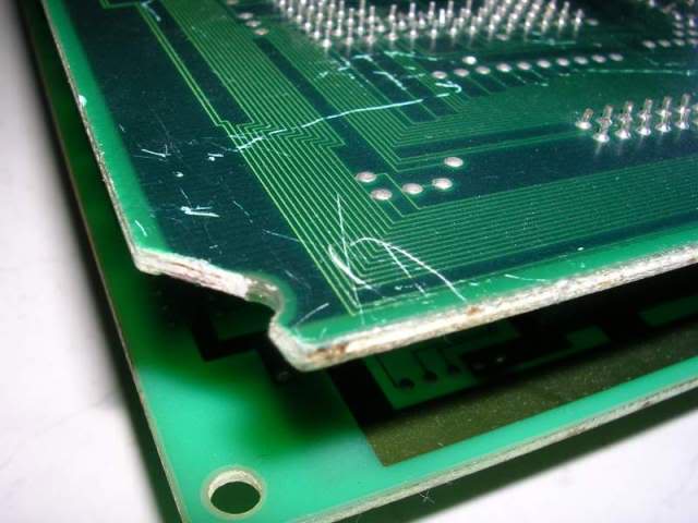
On the solder side the tracks were not near the damage but on the parts side it was a different story, more on that later.
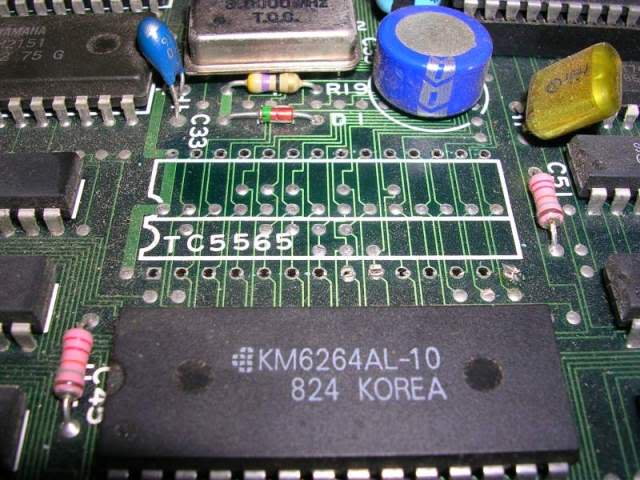
Someone had also removed one of the RAM chips, neatly done but they didn't have enough of a grunty soldering iron to get the ground pin to come free as that was still in the hole and had been chopped off.
Also every single smoothing capacitor had been wrenched off the ROM board, leaving just the legs and the inner plates of each one on the board.
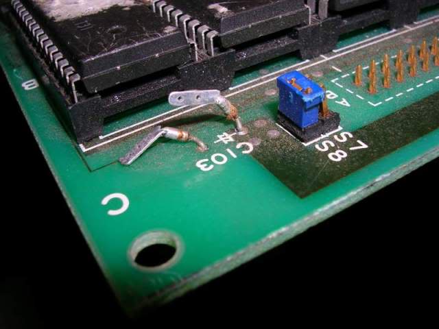
And finally a large number of pins in the service socket had been mashed together.
Oh yeh - and it was filthy.
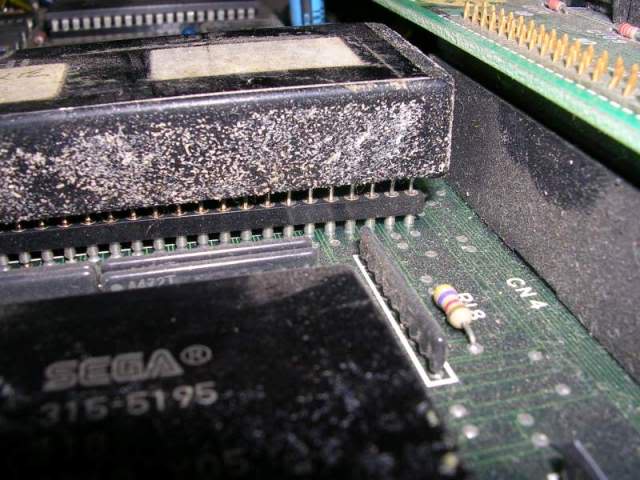
The big black block in this photo is the FD109 decryption CPU block, inside is a modified 68000 CPU, some RAM and a tiny watch battery keeping the RAM alive. The RAM contains a decryption table that untangles the encrypted information stored in the program ROMs, when the battery dies the RAM empties and the CPU gets the encrypted program code direct from the ROMs, without being decrypted this is gibberish to the CPU so the board crashes. I assumed that considering the mess this board was in that the CPU would have suicided - I was wrong. Putting the CPU and the ROM board onto my own System 16 main board gave me a fully working game. Not bad considering that watch battery has been keeping the RAM alive for 21 years now.
Anyway - there was no point powering the board up in its current state, the bent pins risked shorting something out and with only half the system RAM it was never going to work. So I straightened all the pins out in the socket, cleared the remaining solder holes for missing RAM chip and fitted an old dual wipe socket for a 6264 chip. The socket was so I could easily get the chip back as I was not convinced this wasn't a pointless exercise.
I checked against my own board that the long wires soldered to the back of the board were actually needed, that the two endpoints should be joined on a working board and that the link was broken without the wires. You never know what work has been done on a board so its always wise to sanity check someone else's work before applying power.
To rule out any suicide crazyness I also removed the CPU block, installed the 2 decrypted EPROMs and a standard 10MHz 68000 CPU.
After all of that the board booted and ran!!!
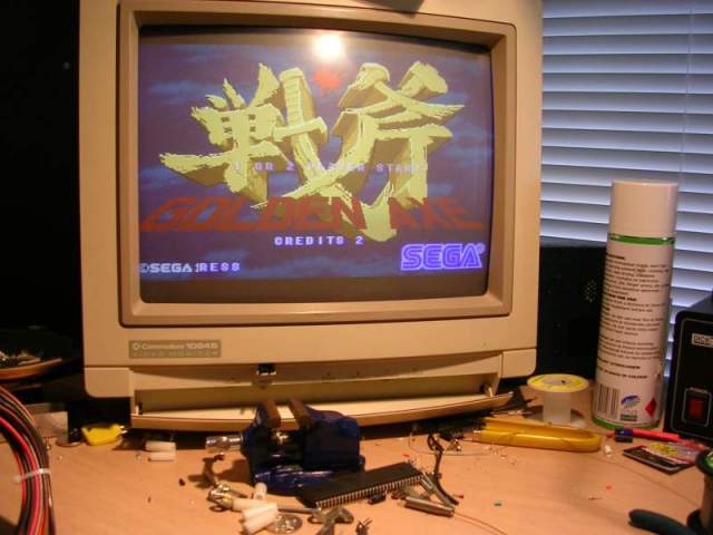
Well kinda, it was mostly OK, it was worryingly silent and some of characters were doing odd things, which I put down to the total lack of smoothing caps on the ROM board.
Next step was the sound, that is after starting up a game to confirm the sound was dead and not just disabled by the dip switches when in attract mode (I could have looked up the dip settings but hitting coin-up was quicker and more conclusive).
First port of call was the Z80 CPU controlling the sound system,
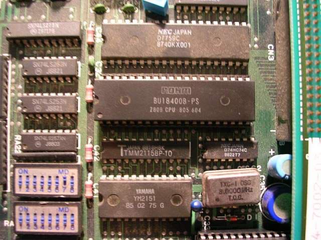
I could see a healthy clock signal on the scope when poking at pin 6 and the RESET and HALT pins at 26 and 18 were logic high (i.e. the CPU enabled). Next was to see what the CPU output looked like, pointing a scope at the data lines showed a pretty messy signal.
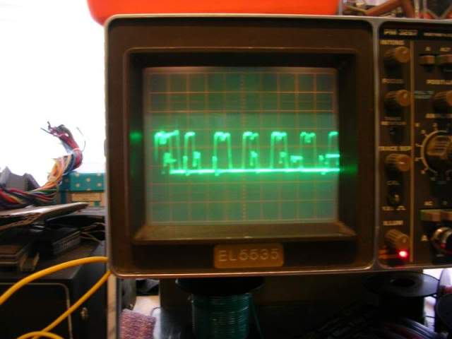
Not a great sign but its amazing what crappy signals can still make perfect sense to the rest of the system when taken in terms of transitions between logic 0 and logic 1. Went on to poke the scope at the address lines and here the issue was very obvious, address lines A7, A8 and A9 were silent and low, yet lines A0-A6 and A10-A15 were active and looked good, either the CPU was totally shot or the address lines were tied somewhere else. The CPU was socketed so easy to remove and test, when put into my Galaxians board which has become my Z80 tester it proved that it was dead. I also suspected the RAM was shot too based on the crappy signals on the scope so I desoldered that but it passed the test on my EPROM burner so a socket was fitted and it went back on the board. With a new Z80 the sound system fired up perfectly.
Next fault was the badly behaving characters in the game, in attract mode it wasn't that evident but when playing a game some characters would come back to life, especially the ones on the pink dinosaurs with the whip tails. When you killed the rider another dinosaur with another rider would appear and sit motionless on the screen. It was impossible to kill him or even touch him, all you got when you tried to attack him was an odd sound effect. The game still thought it was a legit character as you cannot complete the level when he has re spawned as the level is not clear. Impossible to show this with photos so I recorded (badly) it for a laugh.
I put this down to the lack of the four 470uF electrolytic capacitors that are there to fill in any tiny ripples in the power supply to the ROMs, without them the board was susceptible to every flicker on the power rails so its not surprising the logic of the game was less than stable, am surprised it didn't crash to be honest.
Before getting to the caps I decided to straighten out a few mashed jumpers, a couple had been bent so far over that they just fell off as soon as I touched them.
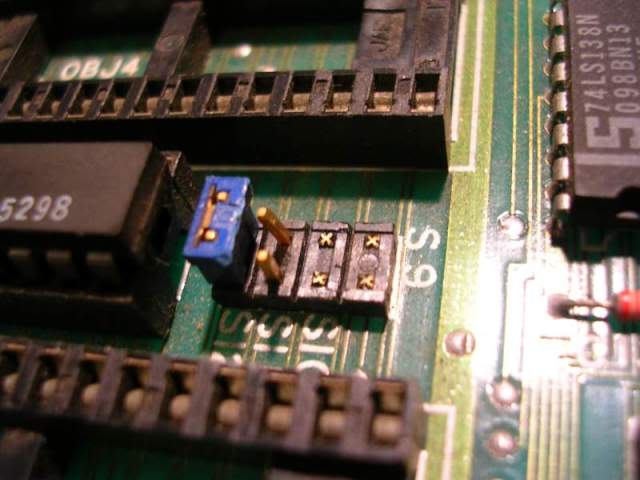
Only one of the missing pair needed to be joined, the jumpers are there to set up the address and data lines for the specific games set of ROMs, different games on this board use different combinations of ROMs so the jumpers allowed Sega to easily use the same PCB for multiple titles. Rather than faff about trying to find the right size pins to put the jumper back I just bent the leg from an LED into a loop around a screwdriver and soldered it in place,
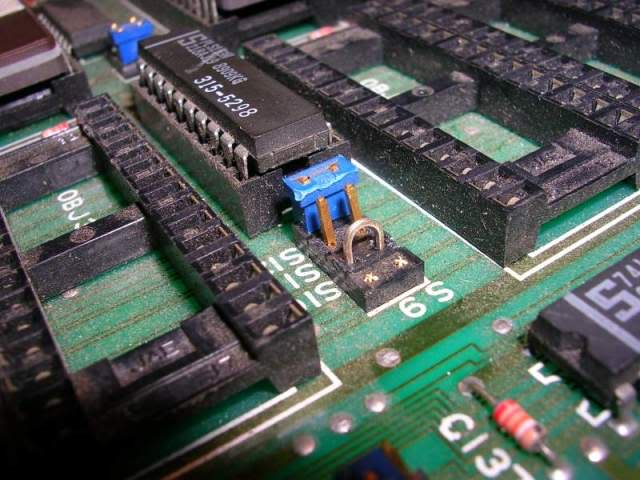
one jumper permanently jumpered!
I desoldered the remains of the old electrolytic caps and fitted 4 new ones, after which the game oddities vanished.
At this point I thought the game totally fixed, but when I went to give it a full test on my cabinet the graphics went nuts, the sprites were torn up and scattered all over the place.
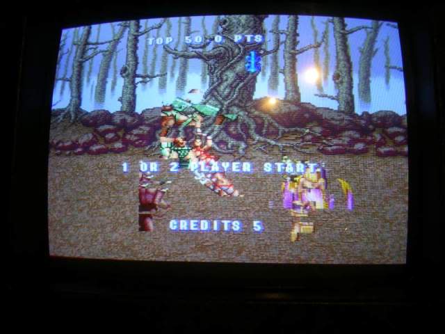
The fault was ultra sensitive to touch, a light pressure on a number of areas of the board would cause it to come and go. Problems like this are a pain in the rear as it very hard to find where the sensitive area actually is as you get a lot of false positives. I thought I had tracked it down to the strangely socketed custom IC that was not actually fully pressed home.
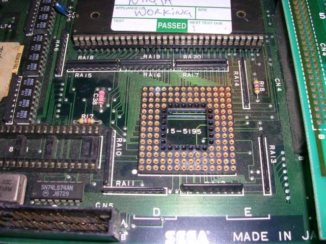
The socket on the board is original but the chip shows signs of being soldered in so its probably not the original chip from this board.
A removal and reseat of this chip didn't improve the issue, but that area of the board no longer seemed to be involved with the issue. After a lot of trial and error I decided it wasn't really an area of the board at fault, more the orientation of the board, when flat on the floor it was sometimes bad, when upside down so I could poke at the solder side it was usually totally fine. I slowly came to suspect it was caused by the long wires on the underside, these were wedged between the pins at a few locations so I supposed there could be a short, or it could simply be cross talk noise. Taking the flying wires off seemed to fix the fault, I have banged and flex and tweaked the board but its rock solid. However without the wires the board was silent again.
The reason was obvious, the soldered one wires went from one of the ROM board connectors to an LS273 in the sound section. With the meter set to continuity beeper I found that of the 8 data inputs on the 273 only 6 went back to the sound EPROM on the ROM board, a couple of data lines on the 8 bit bus were missing, following the tracks for this set of 8 lines took me round the edge of the board straight to the damaged corner, the two outer tracks on the parts side had gone with the missing corner, the inner 6 tracks had survived.
The leads on the back of the board were never a good idea even if they were not shorting out or causing interference, they are far too likely to get caught on something, if the leads had actually followed the original path of the track then they would be 3 times longer as they went all the way round 3 sides of the board. A neater solution was to fix the issue at the site of the damage, a bit fiddly but the two outer tracks are now taken inland around the damaged area and join up again..
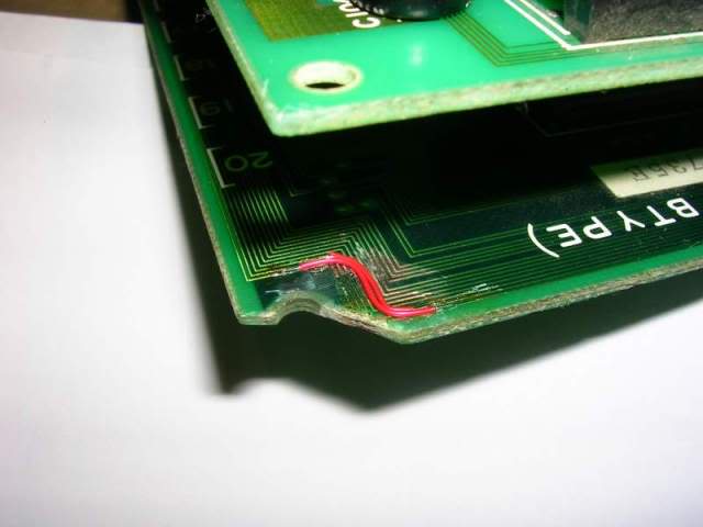
..this will be covered in lacquer ( as will the other scratches) so will be effectively set in concrete, no chance of it getting snagged or shorting out anything.
And that really is about it - the game has now been playing for hours without any issues at all, a bit of a marathon fix but well worth it for a classic.
Board 2
Repairer: Womble
Forum Thread: Golden Axe PCB Repair