Difference between revisions of "PCB Repair Logs Kageki"
m |
m |
||
| Line 17: | Line 17: | ||
'''Repairer:''' [http://www.aussiearcade.com.au/member.php/1983-Womble Womble]<br> | '''Repairer:''' [http://www.aussiearcade.com.au/member.php/1983-Womble Womble]<br> | ||
'''Forum Thread:''' [http://www.aussiearcade.com.au/showthread.php/33714-Taito-Kageki-Repair-Log Kageki PCB Repair]<br> | '''Forum Thread:''' [http://www.aussiearcade.com.au/showthread.php/33714-Taito-Kageki-Repair-Log Kageki PCB Repair]<br> | ||
<br> | |||
Had a few more of Left_jump_left_1P's boards in lately, the ones that had been stored somewhere damp, the first two I looked at were just rotten, corrosion everywhere, wrecked customs, wrecked PCB tracks, totally beyond repair. The third out of the pile was Kageki, a weird-arse Japanese fighting game from Taito | |||
<br> | |||
<br> | |||
[[File:Pcb repair kageki 1.jpg]] | |||
<br> | |||
<br> | <br> | ||
It had some signs of having been somewhere damp, a few chips had very dull oxidised pins, a couple with patches of rust too, but the main give away was a large sticker that had got so wet all the ink had run. | |||
Anyway - fired it up and got a blank screen with scrolling patterns of yellow lines, this was actually a good sign as it suggested the video generation portion of the board was still alive and kicking, just that it was being fed crap, probably. | |||
<br> | |||
<br> | |||
[[File:Pcb repair kageki 2.jpg]] | |||
<br> | |||
<br> | |||
Visually the board was not bad, a bit dusty and but other than the oxidised chip legs... | |||
...there was no physical damage, someone had re soldered a couple of resistor networks and touched up random joints here and there, presumably trying to shot gun fix it. | |||
The first check was that the Z80s were getting a clock signal on pin 6, due to the degree of oxidation on the chip legs it was pretty hard to even get the scope probe to make contact, but in the end all clocks were present. The RESET pin on a single Z80 was bouncing however, which is the watchdog circuit resetting what it sees as a crashed board, the other Z80s were not in reset or halt mode, but were doing nothing. | |||
With a board that's has oxidation evident its likely that all the socketed chips will need to be pulled and reseated, the oxide layer eventually breaks the connection between the pins and the socket, and a reseat scratches it away. It is also a good time to dump the ROMs and compare them to MAME set. The names on the PROMs didn't match the US or Jap MAME set but it was clear who was who, a bank of 8 PROMs for the gfx data, 2 PROMs for the pair of Z80s acting as the main CPUs and a single PROM for the audio CPU. | |||
The main system RAM was also socketed which is unusual, but it meant I could put the chip through my external tester. I had no reason to suspect it and wouldn't have desoldered but it was just too easy to rule out. | |||
Initially I didn''t get very far with dumping the ROMs, the sound CPU PROM was not recognised, neither was one of the main CPU PROMs, thankfully the second one was so I could at least find out what the other half of the data pair was likely to be called. I ignored the gfx data proms as these would mess up the game graphics if they were faulty, they would not stop the board booting. I replaced the faulty PROMs with a couple of 27c512 EPROMs burnt with the right data... | |||
... once these were on board I powered it up and got the exact same fault. | |||
With the software confirmed and the ROMs reseated the next step was back to the CPU. Assuming the one being reset was the master of the paired Z80s (or at least the one that boots first) I went round all the pins... | |||
...it was doing absolutely sod all, no life anywhere. At this point my WCF (well calibrated finger) detected that the chip was stone cold, the other Z80s although doing nothing were at least warm. A cold Z80 that has clock and has been on for a few mins is a dead Z80, so I desoldered it... | |||
<br> | |||
<br> | |||
[[File:Pcb repair kageki 3.jpg]] | |||
<br> | |||
<br> | |||
...whacked it into my Galaxians PCB that has a ZIF socket on it to act as a Z80 tester confirmed it, totally dead. | |||
<br> | |||
<br> | |||
[[File:Pcb repair kageki 4.jpg]] | |||
<br> | |||
<br> | |||
So I fitted a 40 pin socket and dropped in a working Z80-B chip, powered it up and the board booted! | |||
<br> | |||
<br> | |||
[[File:Pcb repair kageki 5.jpg]] | |||
<br> | |||
<br> | |||
[[File:Pcb repair kageki 6.jpg]] | |||
<br> | |||
<br> | |||
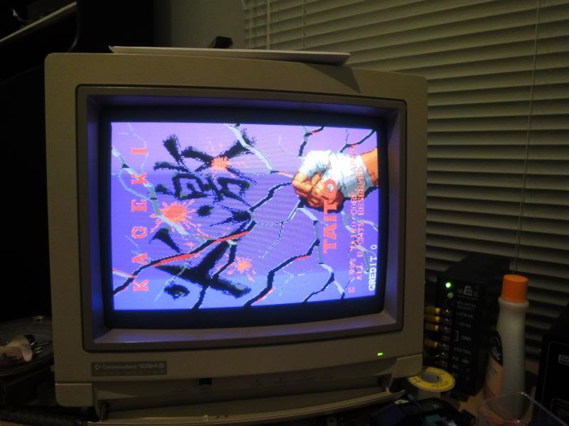
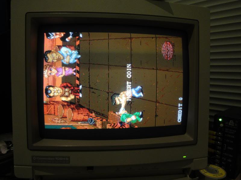
The colours were wrong, it had no sound and it was very crash happy but it was progress. The rest of the issues were simple and painful at the same time. The crashiness is due to the fact its very sensitive to voltage, over voltage makes it very unstable, I had it running at 5.1V and it was not happy. At 4.95 it was rock solid, but it is not unusual for Taito boards to be fussy eaters. The colour issue was because the JAMMA edge fingers were so oxidised my test bench JAMMA connector would not make contact on the red and the blue channel, every now and again it would also lose sync and or video ground for the same reason. Even brasso on the edge connector only improved it slightly, I had to resort to dragging a fine tipped screwdriver over each finger until it was no longer rough, every time I did this a small puff of white dust came off the board. The sound issue was the same fault, the amp was not getting 12V due to the oxide. After a lot of scraping and polishing I eventually got it to work consistently. | |||
<br> | |||
<br> | |||
[[File:Pcb repair kageki 7.jpg]] | |||
<br> | |||
<br> | |||
[[File:Pcb repair kageki 8.jpg]] | |||
<br> | |||
<br> | |||
[[File:Pcb repair kageki 9.jpg]] | |||
<br> | |||
<br> | |||
The only other fault was that one of the gfx roms had a loose 5V pin, it had rusted on the curved shoulder of the leg rather than the point where it entered the chip body. It was easier to fix this chip than to replace it, the MAME set says these are 1Mbit ROMs but the chips on the board are only 28 pin, the only 1Mbit EPROMs I can find info on are 32 pin chips, so these might be mask roms under the stickers. So I resorted to filing back the rust to good metal while the chip was socketed and soldering the joint, it will never be that strong but it doesn't have to be as its in a socket between other socketed chips for protection. | |||
Fixed | |||
<br> | <br> | ||
<br>[[PCB_Repair_Index|Back to PCB Repair Index]] | <br>[[PCB_Repair_Index|Back to PCB Repair Index]] | ||
Revision as of 11:51, 29 August 2012
Kageki
 |
|
| PCB Image | Kageki PCB |
|---|---|
| Pin Out | Reserved |
Repairer: Womble
Forum Thread: Kageki PCB Repair
Had a few more of Left_jump_left_1P's boards in lately, the ones that had been stored somewhere damp, the first two I looked at were just rotten, corrosion everywhere, wrecked customs, wrecked PCB tracks, totally beyond repair. The third out of the pile was Kageki, a weird-arse Japanese fighting game from Taito
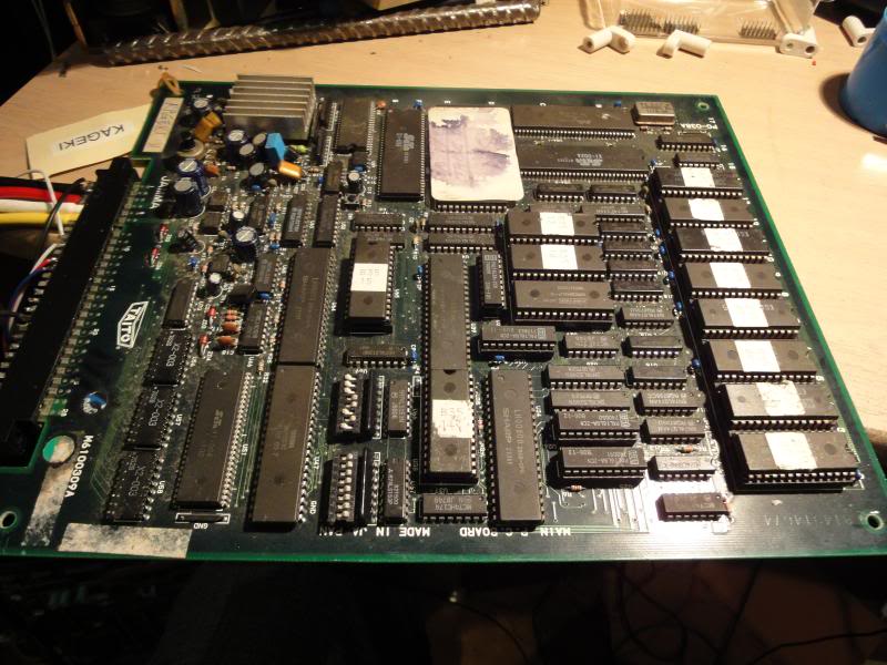
It had some signs of having been somewhere damp, a few chips had very dull oxidised pins, a couple with patches of rust too, but the main give away was a large sticker that had got so wet all the ink had run.
Anyway - fired it up and got a blank screen with scrolling patterns of yellow lines, this was actually a good sign as it suggested the video generation portion of the board was still alive and kicking, just that it was being fed crap, probably.
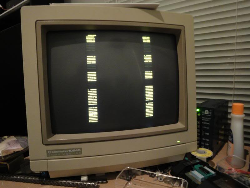
Visually the board was not bad, a bit dusty and but other than the oxidised chip legs...
...there was no physical damage, someone had re soldered a couple of resistor networks and touched up random joints here and there, presumably trying to shot gun fix it.
The first check was that the Z80s were getting a clock signal on pin 6, due to the degree of oxidation on the chip legs it was pretty hard to even get the scope probe to make contact, but in the end all clocks were present. The RESET pin on a single Z80 was bouncing however, which is the watchdog circuit resetting what it sees as a crashed board, the other Z80s were not in reset or halt mode, but were doing nothing.
With a board that's has oxidation evident its likely that all the socketed chips will need to be pulled and reseated, the oxide layer eventually breaks the connection between the pins and the socket, and a reseat scratches it away. It is also a good time to dump the ROMs and compare them to MAME set. The names on the PROMs didn't match the US or Jap MAME set but it was clear who was who, a bank of 8 PROMs for the gfx data, 2 PROMs for the pair of Z80s acting as the main CPUs and a single PROM for the audio CPU.
The main system RAM was also socketed which is unusual, but it meant I could put the chip through my external tester. I had no reason to suspect it and wouldn't have desoldered but it was just too easy to rule out.
Initially I didnt get very far with dumping the ROMs, the sound CPU PROM was not recognised, neither was one of the main CPU PROMs, thankfully the second one was so I could at least find out what the other half of the data pair was likely to be called. I ignored the gfx data proms as these would mess up the game graphics if they were faulty, they would not stop the board booting. I replaced the faulty PROMs with a couple of 27c512 EPROMs burnt with the right data...
... once these were on board I powered it up and got the exact same fault.
With the software confirmed and the ROMs reseated the next step was back to the CPU. Assuming the one being reset was the master of the paired Z80s (or at least the one that boots first) I went round all the pins...
...it was doing absolutely sod all, no life anywhere. At this point my WCF (well calibrated finger) detected that the chip was stone cold, the other Z80s although doing nothing were at least warm. A cold Z80 that has clock and has been on for a few mins is a dead Z80, so I desoldered it...
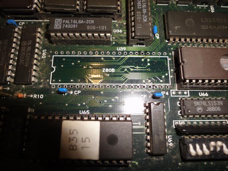
...whacked it into my Galaxians PCB that has a ZIF socket on it to act as a Z80 tester confirmed it, totally dead.
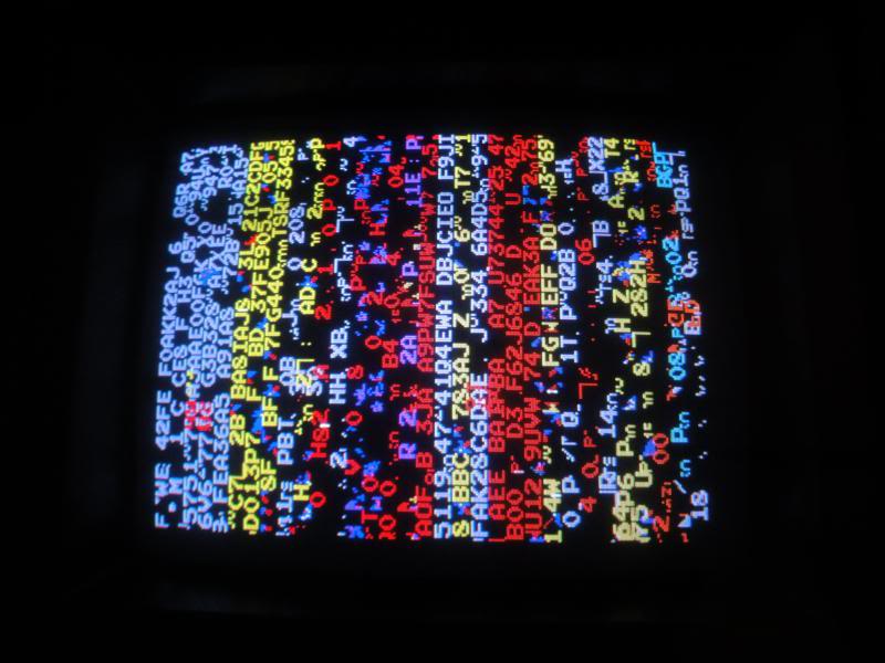
So I fitted a 40 pin socket and dropped in a working Z80-B chip, powered it up and the board booted!
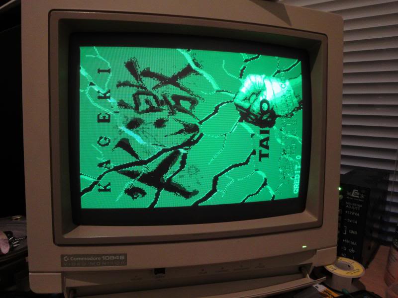
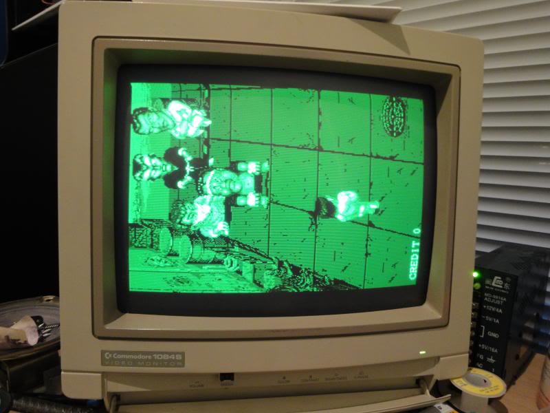
The colours were wrong, it had no sound and it was very crash happy but it was progress. The rest of the issues were simple and painful at the same time. The crashiness is due to the fact its very sensitive to voltage, over voltage makes it very unstable, I had it running at 5.1V and it was not happy. At 4.95 it was rock solid, but it is not unusual for Taito boards to be fussy eaters. The colour issue was because the JAMMA edge fingers were so oxidised my test bench JAMMA connector would not make contact on the red and the blue channel, every now and again it would also lose sync and or video ground for the same reason. Even brasso on the edge connector only improved it slightly, I had to resort to dragging a fine tipped screwdriver over each finger until it was no longer rough, every time I did this a small puff of white dust came off the board. The sound issue was the same fault, the amp was not getting 12V due to the oxide. After a lot of scraping and polishing I eventually got it to work consistently.
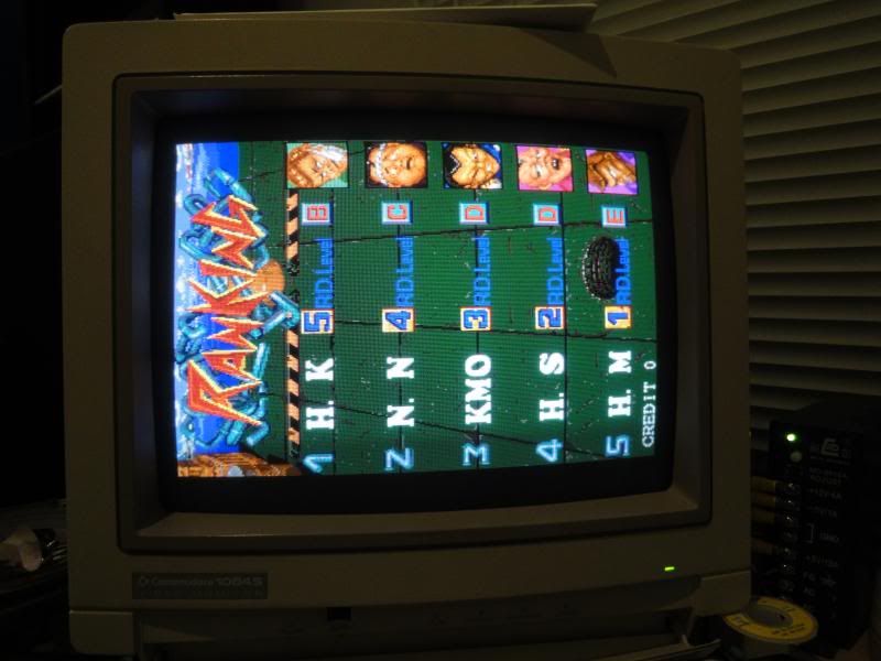
The only other fault was that one of the gfx roms had a loose 5V pin, it had rusted on the curved shoulder of the leg rather than the point where it entered the chip body. It was easier to fix this chip than to replace it, the MAME set says these are 1Mbit ROMs but the chips on the board are only 28 pin, the only 1Mbit EPROMs I can find info on are 32 pin chips, so these might be mask roms under the stickers. So I resorted to filing back the rust to good metal while the chip was socketed and soldering the joint, it will never be that strong but it doesn't have to be as its in a socket between other socketed chips for protection.
Fixed