PCB Repair Logs Esp Ra De: Difference between revisions
Created page with "==ESP Ra. De.== <p><table class="infobox vevent" style="width:22em;" cellspacing="5"> <caption class="summary" style=""><b>ESP Ra. De.</b></caption> <tr class="> <td colspan="..." |
(No difference)
|
Revision as of 12:04, 29 August 2012
ESP Ra. De.
| Esp Ra. De. | |
| PCB Image | Reserved |
|---|---|
| Pin Out | Reserved |
Repairer: Womble
Forum Thread: ESP Ra. De. PCB Repair
Had Bwodie's ESP Ra.De. PCB on the bench this week, its part of a pair (including Do Don Pachi) that he bought working from HK some years back only to have them die on him sometime later.
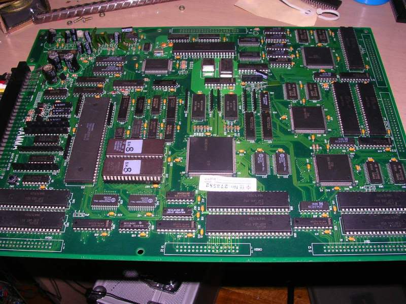
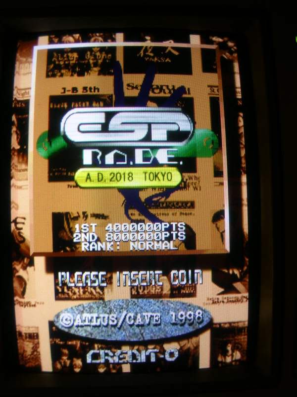
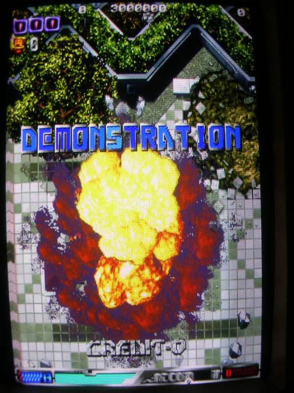
Not being familiar with the game at all it was not immediately obvious what was wrong with it. Obviously the foreground on the title screen was wrong but it was quite neatly wrong. After firing it up in MAME it was obvious what was missing, the game title was chopped up and a few niggly things looked "rough" in game.
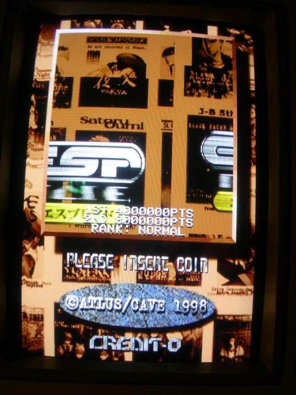
The roughness was impossible to photograph, so much is flying around the screen that the slightest blur made everything look great again so you will have to take my word for that.
I usually don't repair boards that are this late (1998), anythine past the mid 1990s tends to be chock full of custom chips, surface mount devices, including RAM and dozens of honking great mask ROMs,
Masks are far more of a pain than normal roms...
EPROMS - Eraseable Programable Read Only Memory (needs 10 mins of high intensity UV through its window to erase) - Standard Pinouts EEPROMS - Electrically Eraseable Programable Read Only Memory (these chips can be erased using an eprom burner) - Standard Pinouts PROMS - Internally identical to EPROMs but they lack the quartz window so they are only write once devices. - Standard Pinouts MASK ROMs - Similar to ROMs in operation, but they are made with the data fixed into their internal structure. - All pinout bets are off!!
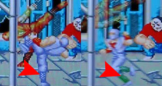
Apparently as prices fell for EPROM technology one constant was the quartz window, so as time went on the window became dispropotionatly expensive. Early boards often were all EPROM based, later boards often only had the game program in EPROMs so any bugs could be fixed easily, the graphics and sound data were unlikely to ever change, even tho sometimes bugs did sneak in like changing shin colour on the main character in Shaddow Warriors depending on what he is doing which was spotted by Frank_fjs.
If you are a board manufacturer planning on producing tens of thousands of boards, using any type of programmable chip is a bit of a pain. You have to buy the blanks in and then program them, it would be better if you could just buy the chips with the code alread built in (this is assuming that the chips were not programmed at the factory - they might have been but again that would have had a dollar cost). So MASK roms started to be used by the bigger companies, MASK roms are made in the same way that CPUs are made, using a light mask through which they shined UV light to react with a layer of photo resist. Areas not masked off from the light ended up being etched away and the pattern left afterwards defined the data the chip contained. Mask roms also have the advantage that you could do away with the need for the pin to support the programming step and as every size jump meant you needed another pin for the upper address line you ended up with a spare pin, as you could only add pins in steps of 2. If your mask happened to be the right size then you could make your chip two pins smaller than a chip that needed programming. You were also not constrained by the standard pinouts either as the chips were custom made for the board you had designed. Obviously it was a cost consideration, making your own mask ROMs is only likely to be worthwhile for very large production runs, but once you get there it was obviously cheaper than buying PROMs and programming them.
Anyway - back to the board, this board was wall to wall PROMs, or MASKs, its hard to tell sometimes. The only way to be sure is to look at the pinout and in this case I didnt have the pinout to start with. All I could go on was which pins were tied to 5V, which were grounded, and which showed data on the scope. The chip markings were no help, they were custom printed for this board so I started off assuming they were masks. To cut a very long story short - I was wrong, they were PROMS, big buggers, 32MBit PROMs, 42 pin monsters.
Once I had the pinout I could start poking around the address and data lines, which allowed me to narrow down the pair at the bottom right of the board.
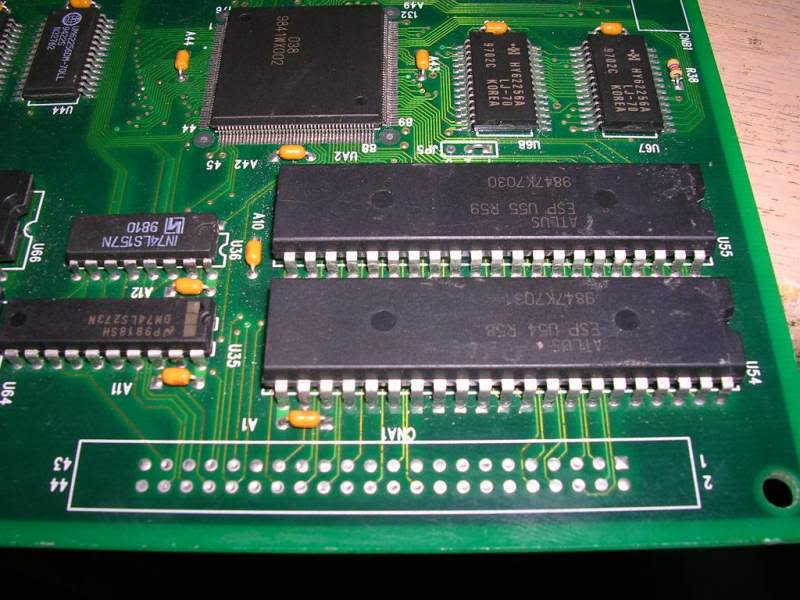
The 2 PROMs I now suspected were obviously working correctly for the most part, if I interupted the address bus to them then things got a whole lot worse on screen.
Now I had the pinout I could desolder the PROMs and dump them, U54 dumped and was not recognised at all, U55 was flagged as missing address line A18 and again gave a dump that was not recognised.
Fast forward a week or two and I had some 27C322s to work with, due to the sheer size of these buggers it took my burner ten minutes to erase-check, burn and verify each one.
>>Load File OK! Time:24/12/1996 11:32:00 PM >> 0.02Sec
>>.Blank Check...... >>Blank Check OK! >>.Program...... >>.Verify...... >>Program OK! >> 626.23Sec
I fitted a couple of 40 pin machined pin sockets to the board, and cut two single pins from a SIL strip I had kicking around to form the lower pins giving a total of 42 pins.
Slapped the burnt 27c322s in....
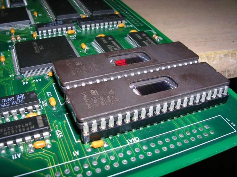
....and fired her up.
Just got to print some EPROM stickers to cover the windows and she's ready to go home
