PCB Repair Logs Fighting Soccer Bootleg: Difference between revisions
mNo edit summary |
No edit summary |
||
| (One intermediate revision by the same user not shown) | |||
| Line 23: | Line 23: | ||
<br> | <br> | ||
<br> | <br> | ||
[[File:Pcb repair | [[File:Pcb repair fighting soccer bootleg 1.jpg]] | ||
<br> | <br> | ||
<br> | <br> | ||
And had someone tried to drill holes in the PCB??? | And had someone tried to drill holes in the PCB??? | ||
<br> | <br> | ||
<br> | <br> | ||
[[File:Pcb repair | [[File:Pcb repair fighting soccer bootleg 2.jpg]] | ||
<br> | <br> | ||
<br> | <br> | ||
| Line 37: | Line 36: | ||
<br> | <br> | ||
<br> | <br> | ||
[[File:Pcb repair | [[File:Pcb repair fighting soccer bootleg 3.jpg]] | ||
<br> | <br> | ||
<br> | <br> | ||
Without getting my hopes up too high, I replaced the broken cap and hooked the poor thing up in the bench. Well first thing I noticed: No sound! But when I turned the volume pot on the board up, I did hear a hissing sound (It Still Alive };-)). Hmmm, a fast check with the voltmeter and it was obvious that this board didn't get -5V. Soon I found out why?! My JAMMA-extender didn't have -5V wired (note to self: Why do you keep buying premade stuff, that you could have done better yourself? Grrrr). Tried to hook up the board directly in the benches JAMMA-slot... | Without getting my hopes up too high, I replaced the broken cap and hooked the poor thing up in the bench. Well first thing I noticed: No sound! But when I turned the volume pot on the board up, I did hear a hissing sound (It Still Alive };-)). Hmmm, a fast check with the voltmeter and it was obvious that this board didn't get -5V. Soon I found out why?! My JAMMA-extender didn't have -5V wired (note to self: Why do you keep buying premade stuff, that you could have done better yourself? Grrrr). Tried to hook up the board directly in the benches JAMMA-slot... | ||
<br> | <br> | ||
<br> | <br> | ||
[[File:Pcb repair | [[File:Pcb repair fighting soccer bootleg 4.jpg]] | ||
<br> | <br> | ||
<br> | <br> | ||
...and heard the well known SNK-boot-jingle from the speakers };-D | ...and heard the well known SNK-boot-jingle from the speakers };-D | ||
Wired the -5V on the extender and hooked the board up again. | Wired the -5V on the extender and hooked the board up again. | ||
| Line 53: | Line 50: | ||
<br> | <br> | ||
<br> | <br> | ||
[[File:Pcb repair | [[File:Pcb repair fighting soccer bootleg 5.jpg]] | ||
<br> | |||
<br> | |||
<br> | <br> | ||
<br> | <br> | ||
[[File:Pcb repair fighting soccer bootleg 6.jpg]] | |||
[[File:Pcb repair | |||
<br> | <br> | ||
<br> | <br> | ||
[[File:Pcb repair fighting soccer bootleg 7.jpg]] | |||
[[File:Pcb repair | |||
<br> | <br> | ||
<br> | <br> | ||
By shortening adjacent pins on different RAMs and ROMs I quickly saw, that the graphics was (as with most boards with 2 PCBs) handled by the secondary PCB. So tested all data and address pins on the RAMs and ROMs with the scope, but found no oddyties. | By shortening adjacent pins on different RAMs and ROMs I quickly saw, that the graphics was (as with most boards with 2 PCBs) handled by the secondary PCB. So tested all data and address pins on the RAMs and ROMs with the scope, but found no oddyties. | ||
Now, it way getting late and I felt a bit tired. I did however decide to do a little piggy-backing of TTLs before going to bed. The board have a cluster of 3 245's in the middle and I just happen to have a tube of them on the table, so I thougth: Let's give it a try: | Now, it way getting late and I felt a bit tired. I did however decide to do a little piggy-backing of TTLs before going to bed. The board have a cluster of 3 245's in the middle and I just happen to have a tube of them on the table, so I thougth: Let's give it a try: | ||
<br> | <br> | ||
<br> | <br> | ||
[[File:Pcb repair | [[File:Pcb repair fighting soccer bootleg 8.jpg]] | ||
<br> | <br> | ||
<br> | <br> | ||
| Line 83: | Line 79: | ||
<br> | <br> | ||
<br> | <br> | ||
[[File:Pcb repair | [[File:Pcb repair fighting soccer bootleg 9.jpg]] | ||
<br> | <br> | ||
<br> | <br> | ||
| Line 92: | Line 88: | ||
<br> | <br> | ||
<br> | <br> | ||
[[File:Pcb repair | [[File:Pcb repair fighting soccer bootleg 10.jpg]] | ||
<br> | <br> | ||
<br> | <br> | ||
| Line 101: | Line 97: | ||
<br> | <br> | ||
<br> | <br> | ||
[[File:Pcb repair | [[File:Pcb repair fighting soccer bootleg 11.jpg]] | ||
<br> | <br> | ||
<br> | <br> | ||
| Line 110: | Line 106: | ||
<br> | <br> | ||
<br> | <br> | ||
[[File:Pcb repair | [[File:Pcb repair fighting soccer bootleg 12.jpg]] | ||
<br> | <br> | ||
<br> | <br> | ||
| Line 117: | Line 113: | ||
<br> | <br> | ||
<br> | <br> | ||
[[File:Pcb repair | [[File:Pcb repair fighting soccer bootleg 13.jpg]] | ||
<br> | <br> | ||
<br> | <br> | ||
| Line 124: | Line 120: | ||
<br> | <br> | ||
<br> | <br> | ||
[[File:Pcb repair | [[File:Pcb repair fighting soccer bootleg 14.jpg]] | ||
<br> | <br> | ||
<br> | <br> | ||
| Line 131: | Line 127: | ||
<br> | <br> | ||
<br> | <br> | ||
[[File:Pcb repair | [[File:Pcb repair fighting soccer bootleg 15.jpg]] | ||
<br> | <br> | ||
<br> | <br> | ||
[[File:Pcb repair fighting soccer bootleg 16.jpg]] | |||
[[File:Pcb repair | |||
<br> | <br> | ||
<br> | <br> | ||
| Line 142: | Line 137: | ||
<br> | <br> | ||
<br> | <br> | ||
[[File:Pcb repair | [[File:Pcb repair fighting soccer bootleg 17.jpg]] | ||
<br> | <br> | ||
<br> | <br> | ||
<br>[[PCB_Repair_Index|Back to PCB Repair Index]] | <br>[[PCB_Repair_Index|Back to PCB Repair Index]] | ||
Latest revision as of 11:24, 5 September 2012
Fighting Soccer (Bootleg)
| File:Marquee fighting soccer.jpg | |
| PCB Image | Reserved |
|---|---|
| Pin Out | Reserved |
Repairer: Elgen
Forum Thread: Fighting Soccer (Bootleg) PCB Repair
Now this board is a relatively new investment (from the same batch as M.I.A. http://elgensrepairs.blogspot.com/20...a-rep-log.html). A bootleg of SNK's Fighting Soccer. Before even connecting it, I could see that it have seen better days.
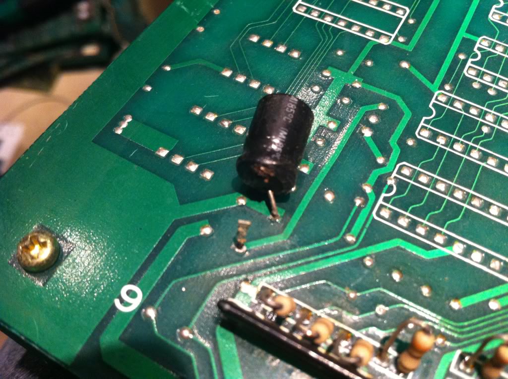
Here a broken cappy...
And had someone tried to drill holes in the PCB???
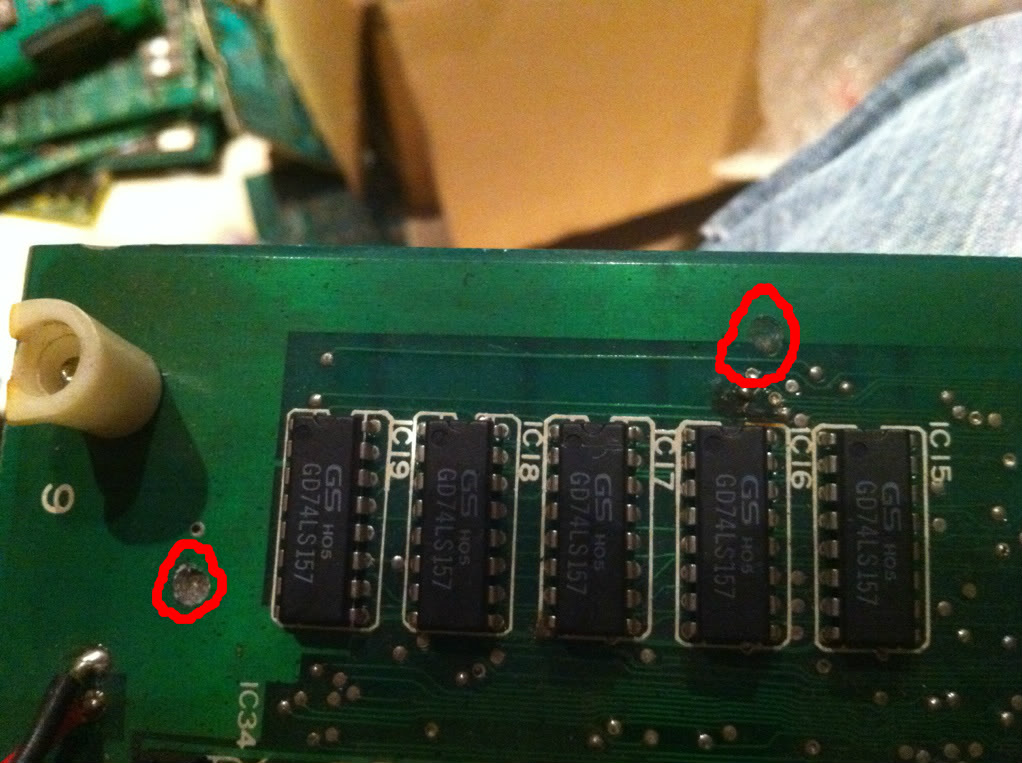
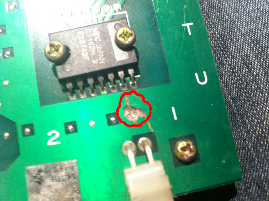
...not only two but THREE PLACES...WTF?!
Without getting my hopes up too high, I replaced the broken cap and hooked the poor thing up in the bench. Well first thing I noticed: No sound! But when I turned the volume pot on the board up, I did hear a hissing sound (It Still Alive };-)). Hmmm, a fast check with the voltmeter and it was obvious that this board didn't get -5V. Soon I found out why?! My JAMMA-extender didn't have -5V wired (note to self: Why do you keep buying premade stuff, that you could have done better yourself? Grrrr). Tried to hook up the board directly in the benches JAMMA-slot...
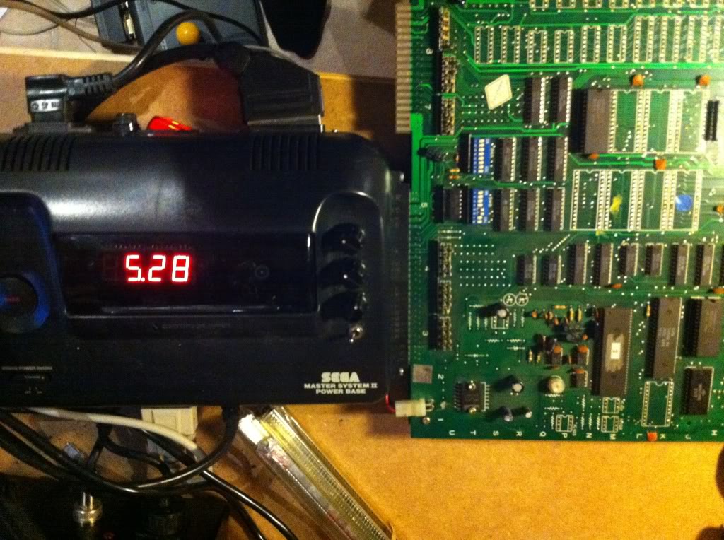
...and heard the well known SNK-boot-jingle from the speakers };-D
Wired the -5V on the extender and hooked the board up again.
A lot of the sprites had horizontal stripes through them.
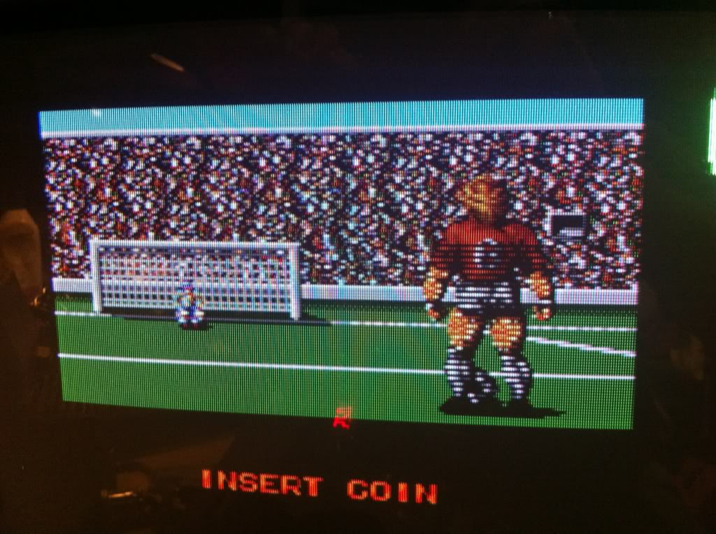
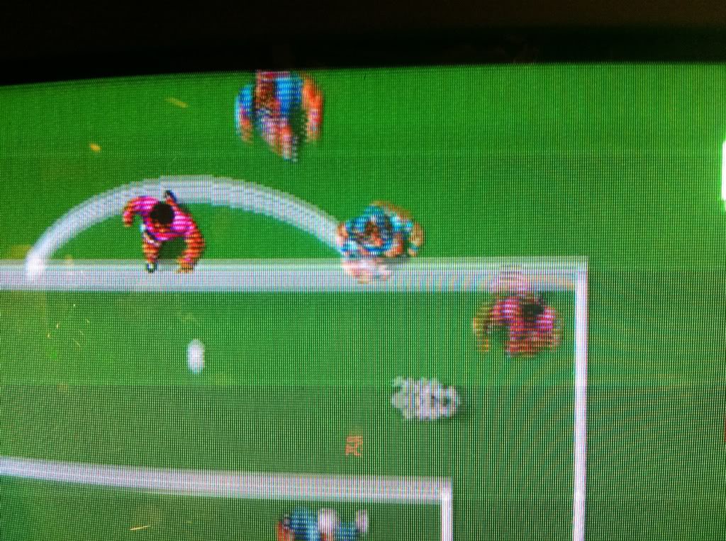
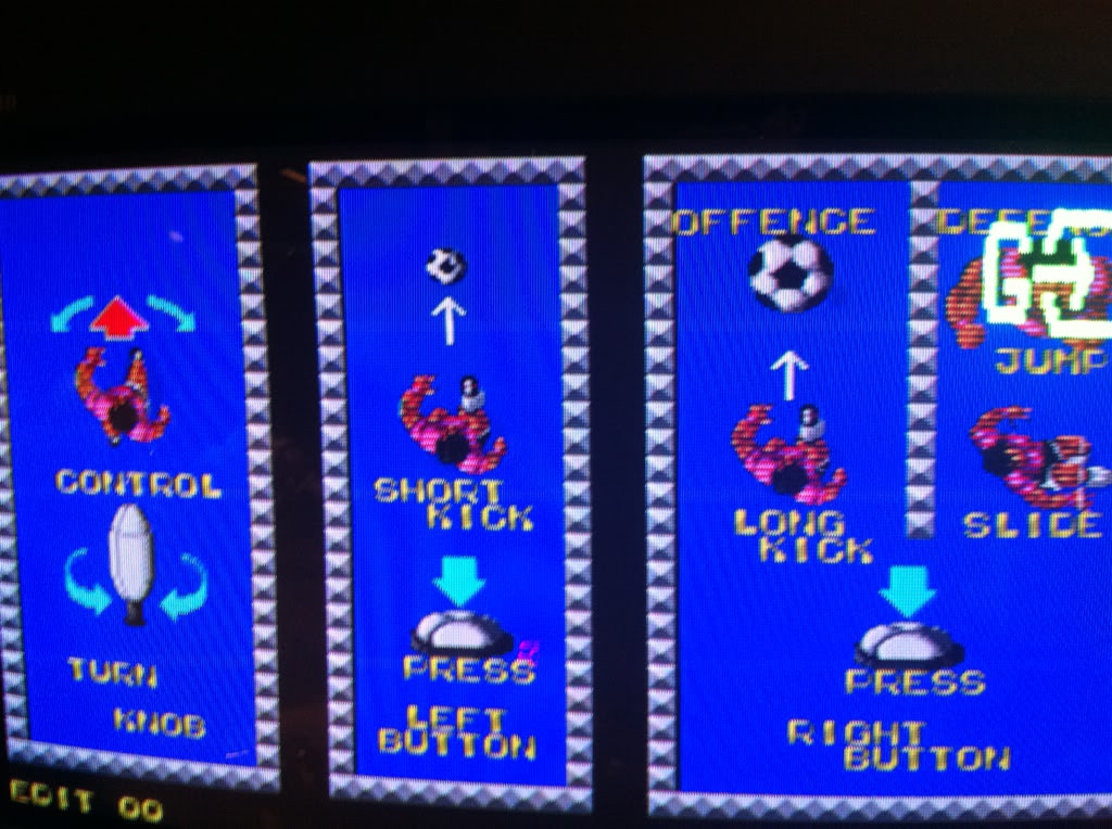
By shortening adjacent pins on different RAMs and ROMs I quickly saw, that the graphics was (as with most boards with 2 PCBs) handled by the secondary PCB. So tested all data and address pins on the RAMs and ROMs with the scope, but found no oddyties.
Now, it way getting late and I felt a bit tired. I did however decide to do a little piggy-backing of TTLs before going to bed. The board have a cluster of 3 245's in the middle and I just happen to have a tube of them on the table, so I thougth: Let's give it a try:
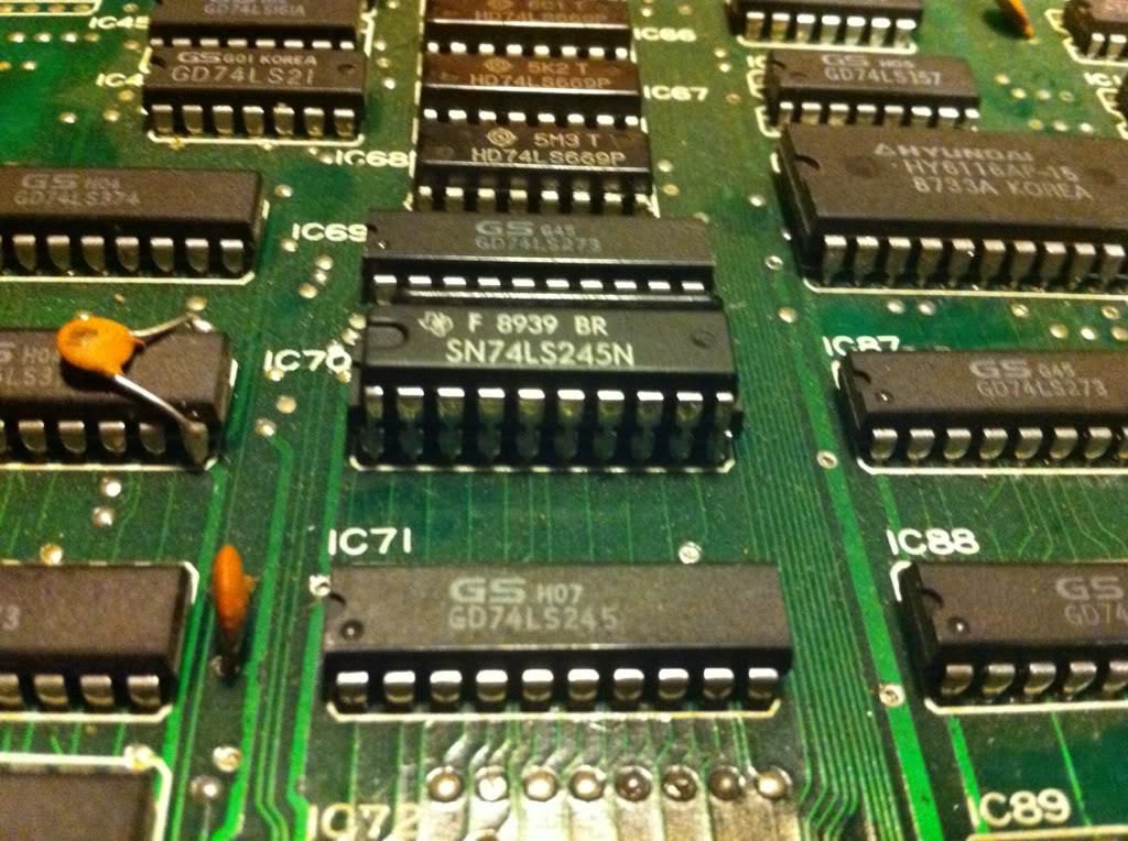
...and to my big surprise, all sprites looked normal again. Quite a lucky punch (I so i thougth!).
I quickly desoldered the IC and put it in my Top2005+ for testing...hmm, the test came out successful??? The one I've used for piggy-back (the one from tube) also passed the test.
Fitted a socket and inserted the new one: Stripes through sprites!
Inserted the old one back into the socket: Stripes through sprites!!
Piggy-backed the new one on top of the old one: Still stripes through sprites!!!
(BTW: Did you notice that the words "sprites" and "stripes" have the exact same letters...kind'o'funny };-P).
Now I was really puzzled...Then tried piggy-backing the new on top of the 2nd 245 in the batch of 3: No stripes??? WTF!
I wanted to get to the bottom of this, so desoldered the 2 others as well and fitted sockets.
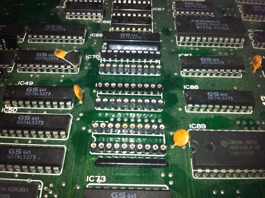
Slammed in 3 new ones from the tube: Stripes!
Put the old ones back: Stripes! (MOAN!)
I discovered that one of the 245's wasn't inserted fully into the socket. With the board still running I gave it a push, and the stripes went away?! Released the pressure and stripes came back. Began pressing on IC's in the surrounding area: Same thing happend!!!
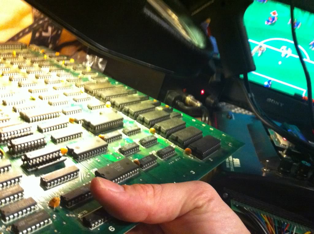
Picked up the board and bended it slightly with the same result.
Now we are getting somewhere; this smelled an awful lot like a short-circuit of some sort.
When looking closely at the joints on the solderside, there was alot of them looking very nasty:
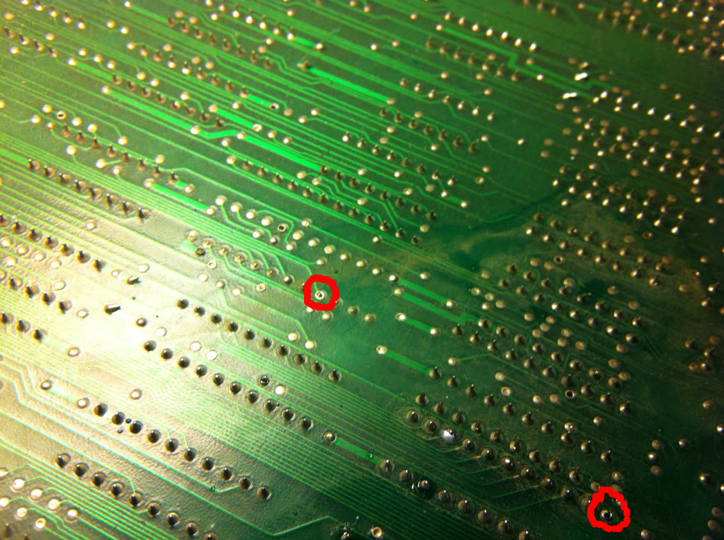
This is just 2 examples, but this board has extremely many of them.
So started a shotgun-scheme, where I did a reflow on the nasty joints I could see checking the board every time. After about 10 of them with no luck, I decided to change strategy into a more systematic brute-force approach.
Started by cleaning the lower half of the board using rubbing alcohol and a toothbrush.
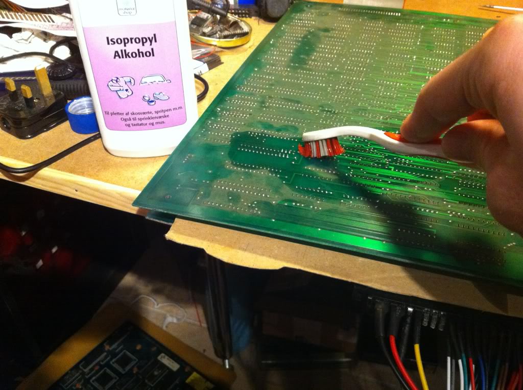
Then starting at ground-zero (the place where I had to apply the least pressure to provoke the fault), I began the process of reflowing the joints on every IC while working my way to the edges of the board. After having done an IC, I tested the board. And on the 18th IC I hit the jackpot!
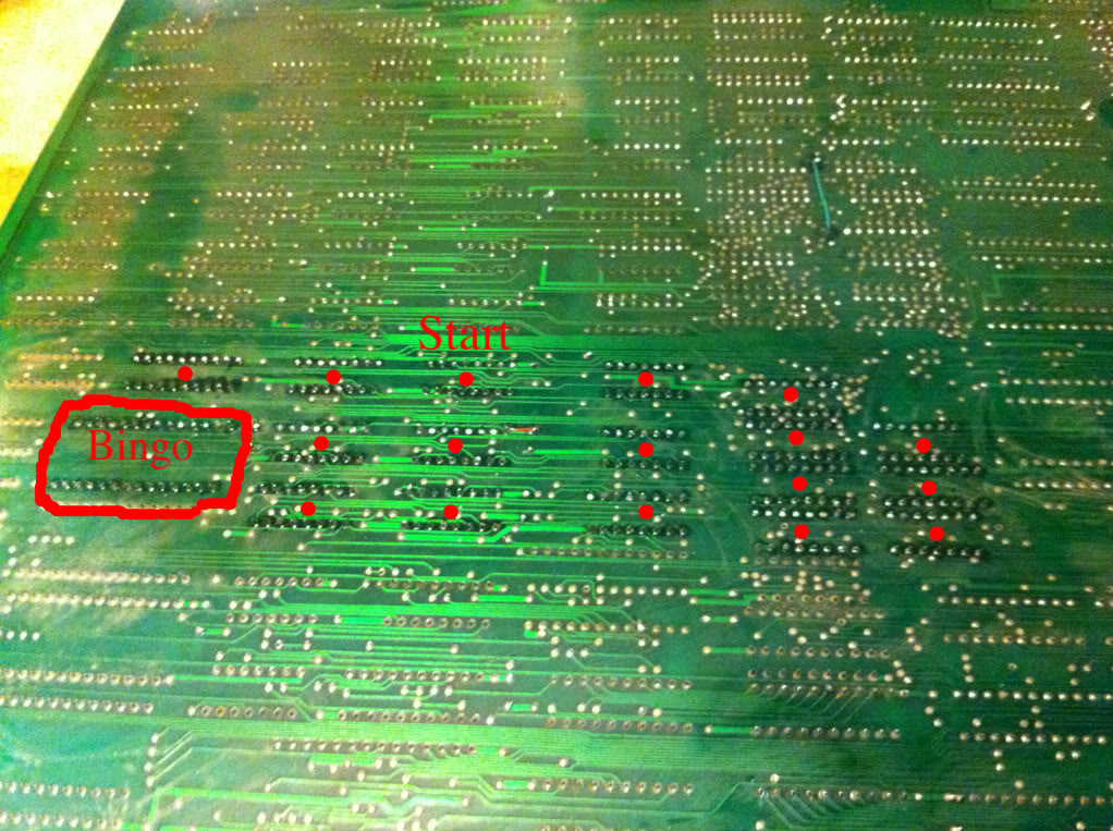
It was this PROM who was the little troublemaker };-)
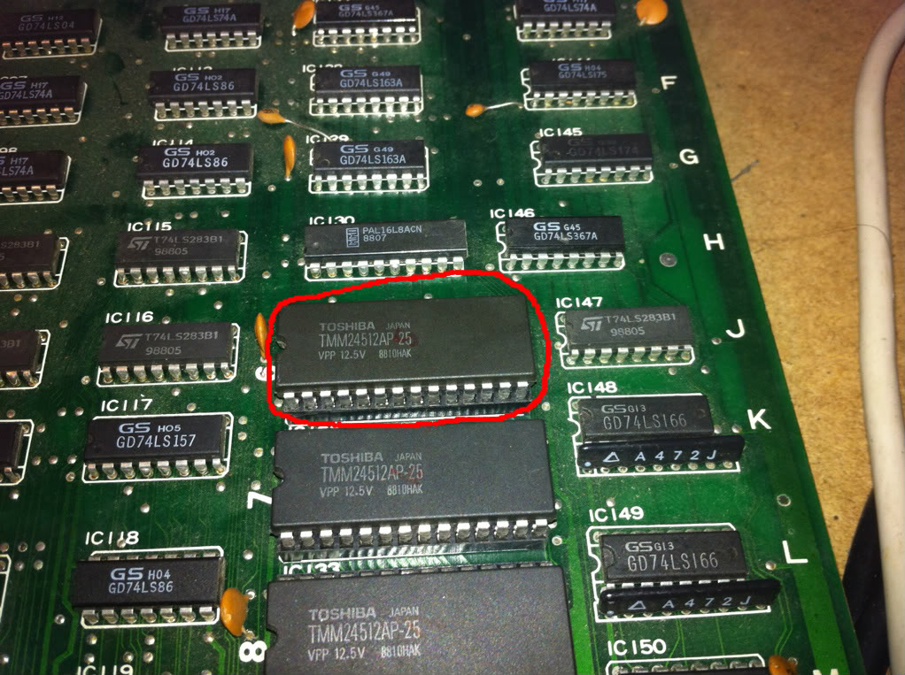
And now all the sprites looked good at all times };-D
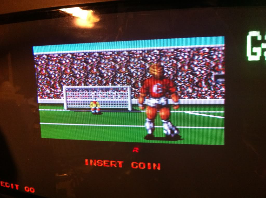
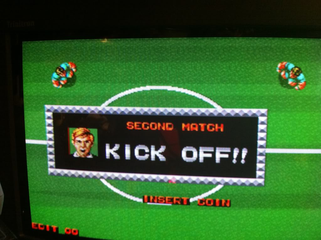
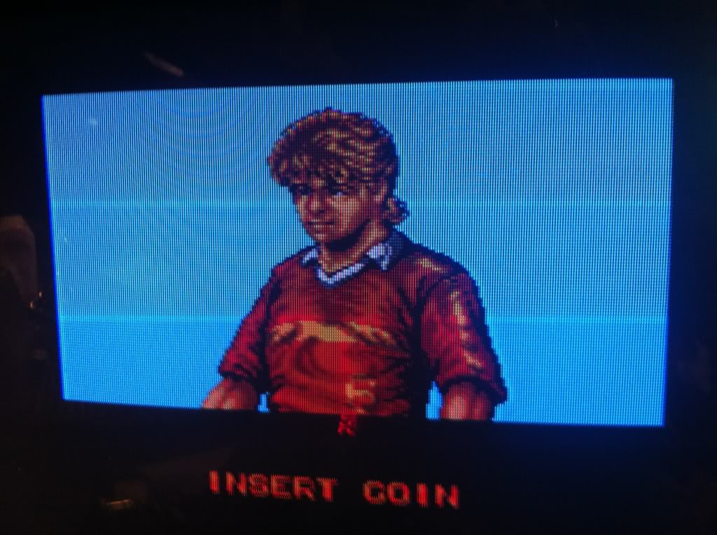
Just before I close this log off, I'd like to share with you all this piece of beautiful hairdresser art };-P
