PCB Repair Logs Double Dragon Bootleg: Difference between revisions
mNo edit summary |
mNo edit summary |
||
| Line 18: | Line 18: | ||
'''Forum Thread:''' [http://www.aussiearcade.com.au/showthread.php/46401-Taito-Double-Dragon-Bootleg-Repair-Log Double Dragon (Bootleg) PCB Repair]<br> | '''Forum Thread:''' [http://www.aussiearcade.com.au/showthread.php/46401-Taito-Double-Dragon-Bootleg-Repair-Log Double Dragon (Bootleg) PCB Repair]<br> | ||
<br> | <br> | ||
This game is a true 80's classic (well at least around Roskilde, Denmark where I grew up). Back then almost all of my arcade gaming was done at burger joints with names like: Torvegrillen, Burger Place, Burger Boss, and Wopsi Burger. The latter was the best as it had 10+ standard cabinets with games changing about once a month... | |||
Well enough nostalgia for this post; I proudly present (a bootleg of): Double Dragon! | |||
I bought this just a few days ago, and by the symptoms it looked like an easy fix, so I started right away. A self test looking like this is always a good sign. | |||
<br> | |||
<br> | |||
[[File:Pcb repair double dragon bootleg 1.jpg]] | |||
<br> | |||
<br> | |||
...but then trouble started. An intro screen looking like this: | |||
<br> | |||
<br> | |||
[[File:Pcb repair double dragon bootleg 2.jpg]] | |||
<br> | |||
<br> | |||
Also the sprites where pretty messed up with stripes through them and some parts misplaced: | |||
<br> | |||
<br> | |||
[[File:Pcb repair double dragon bootleg 3.jpg]] | |||
<br> | |||
<br> | |||
And the game had no sound at all! | |||
Well easy to see that these two cabs in the sound section had seen better days | |||
<br> | |||
<br> | |||
[[File:Pcb repair double dragon bootleg 4.jpg]] | |||
<br> | |||
<br> | |||
and not all that surprisingly, changing them brougth the sound back };-) | |||
<br> | |||
<br> | |||
[[File:Pcb repair double dragon bootleg 5.jpg]] | |||
<br> | |||
<br> | |||
The board had some other obvious physical damages that needed fixing. | |||
Here a knocked-off smoothening cap | |||
<br> | |||
<br> | |||
[[File:Pcb repair double dragon bootleg 6.jpg]] | |||
<br> | |||
<br> | |||
[[File:Pcb repair double dragon bootleg 7.jpg]] | |||
<br> | |||
<br> | |||
1 transistor with 2 pins ripped off and the other one missing all together | |||
<br> | |||
<br> | |||
[[File:Pcb repair double dragon bootleg 8.jpg]] | |||
<br> | |||
<br> | |||
[[File:Pcb repair double dragon bootleg 9.jpg]] | |||
<br> | |||
<br> | |||
A physically broken 157; the 04 just beside it had also taken a big knock at some point and was replaced for good measure as well. Both spares was taken from scrap boards. | |||
<br> | |||
<br> | |||
[[File:Pcb repair double dragon bootleg 10.jpg]] | |||
<br> | |||
<br> | |||
[[File:Pcb repair double dragon bootleg 11.jpg]] | |||
<br> | |||
<br> | |||
Now I did expect to see some kind of change when replacing the broken 157, but not the kind that I saw when hooking the board up again... | |||
<br> | |||
<br> | |||
[[File:Pcb repair double dragon bootleg 12.jpg]] | |||
<br> | |||
<br> | |||
Hmmm, must have done something wrong when fitting them sockets. Pulled the 157 again and had a look. Now I really appreciated myself for always using breakable header sockets instead of normal sockets, as this gave my a clear look down between the two rows. I found one of the tracks between a via and one of the pins suspicious, and the continuity tester confirmed my hunch. | |||
<br> | |||
<br> | |||
[[File:Pcb repair double dragon bootleg 13.jpg]] | |||
<br> | |||
<br> | |||
Patched it up with a little piece of kynar on the solderside. | |||
<br> | |||
<br> | |||
[[File:Pcb repair double dragon bootleg 14.jpg]] | |||
<br> | |||
<br> | |||
Now the boot error had gone, but there was still no change in regards to the graphics on screen. | |||
Until now I had only concentrated on the primary PCB, so now I had a look at the secondary one. The component side looked incredibly fine, considering the damages found on the primary one. The solder side however had a fair among of scratches and was also pretty dirty. | |||
<br> | |||
<br> | |||
[[File:Pcb repair double dragon bootleg 15.jpg]] | |||
<br> | |||
<br> | |||
I gave the worst place a light scrup with rubbing alcohol and tooth brush, and I found 1 pin touching a nearby via and a track that was scratched in 3 places. Again the continuity tester confirmed... | |||
<br> | |||
<br> | |||
[[File:Pcb repair double dragon bootleg 16.jpg]] | |||
<br> | |||
<br> | |||
So straitened the pin (along with about 5 others that I found, for good measure) with a Stanley knife a alot of caution. Then patched the broken track with kynar. | |||
<br> | |||
<br> | |||
[[File:Pcb repair double dragon bootleg 17.jpg]] | |||
<br> | |||
<br> | |||
And NOW, the intro screen | |||
<br> | |||
<br> | |||
[[File:Pcb repair double dragon bootleg 18.jpg]] | |||
<br> | |||
<br> | |||
and the sprites where alive and kicking again };-) | |||
(please take note of the cute up-skirt view you get in this pic };-P). | |||
<br> | |||
<br> | |||
[[File:Pcb repair double dragon bootleg 19.jpg]] | |||
<br> | |||
<br> | |||
Now all was good, and I started test-playing the game. But when I tried a 2-player game, the hit-button for player-2 was unresponsive. A quick glance at the input section on the primary PCB, and my eyes caught this broken resistor array. | |||
<br> | |||
<br> | |||
[[File:Pcb repair double dragon bootleg 20.jpg]] | |||
<br> | |||
<br> | |||
By measuring on one it's sisters, I found that this was not the same type as nomally used for pull-ups (with a common point). It was more like 4 parallel resistors just packed into one house. I couldn't find any of those on any of my scraps, so desided on just fitting 4 standard 220Ohms resistors. Now the original bootleggers had put 2 componentpins into each hole, but with the pin-diameter of the standard resistors, I had no chance of doing that. So I desoldered the standard pull-up array | |||
<br> | |||
<br> | |||
[[File:Pcb repair double dragon bootleg 21.jpg]] | |||
<br> | |||
<br> | |||
and resoldered it so that it was possible to access the pins from the component side. Then I soldered the 4 standard resistors directly on the pins from the component side. | |||
<br> | |||
<br> | |||
[[File:Pcb repair double dragon bootleg 22.jpg]] | |||
<br> | |||
<br> | |||
And once again our Red Hero is able to swing his pork chop against the baddies };-P | |||
<br> | |||
<br> | |||
[[File:Pcb repair double dragon bootleg 23.jpg]] | |||
<br> | |||
<br> | |||
And finally this case is closed };-D | |||
<br> | <br> | ||
<br>[[PCB_Repair_Index|Back to PCB Repair Index]] | <br>[[PCB_Repair_Index|Back to PCB Repair Index]] | ||
Latest revision as of 11:47, 5 September 2012
Double Dragon (Bootleg)
 |
|
| PCB Image | Reserved |
|---|---|
| Pin Out | Reserved |
Repairer: Elgen
Forum Thread: Double Dragon (Bootleg) PCB Repair
This game is a true 80's classic (well at least around Roskilde, Denmark where I grew up). Back then almost all of my arcade gaming was done at burger joints with names like: Torvegrillen, Burger Place, Burger Boss, and Wopsi Burger. The latter was the best as it had 10+ standard cabinets with games changing about once a month...
Well enough nostalgia for this post; I proudly present (a bootleg of): Double Dragon!
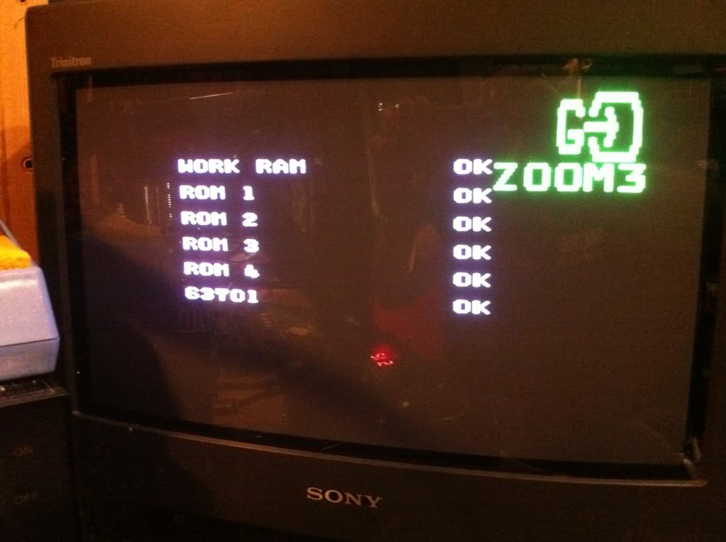
I bought this just a few days ago, and by the symptoms it looked like an easy fix, so I started right away. A self test looking like this is always a good sign.
...but then trouble started. An intro screen looking like this:
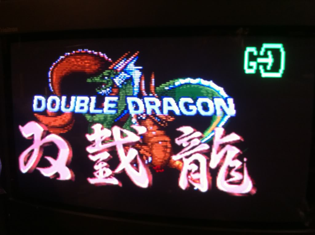
Also the sprites where pretty messed up with stripes through them and some parts misplaced:
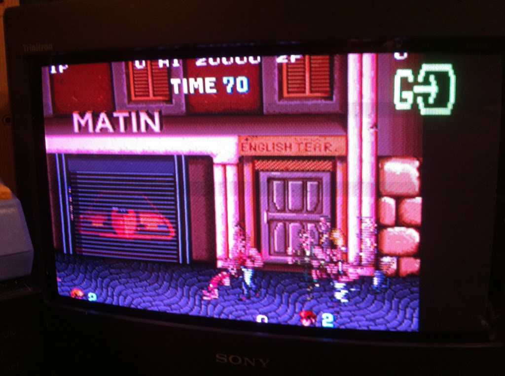
And the game had no sound at all!
Well easy to see that these two cabs in the sound section had seen better days
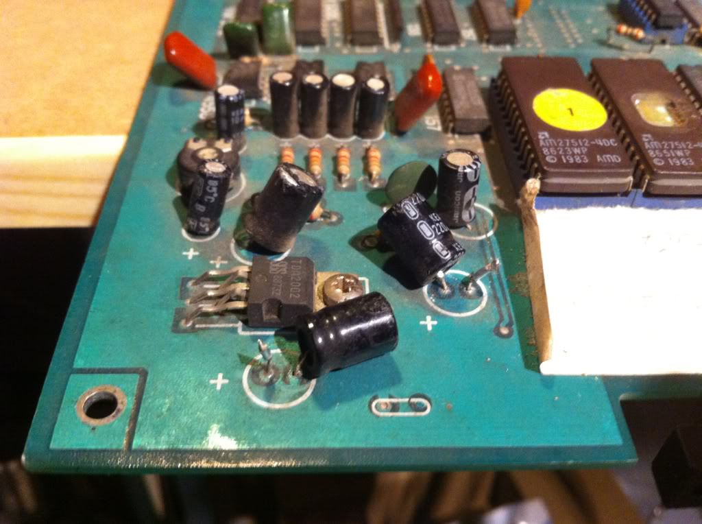
and not all that surprisingly, changing them brougth the sound back };-)
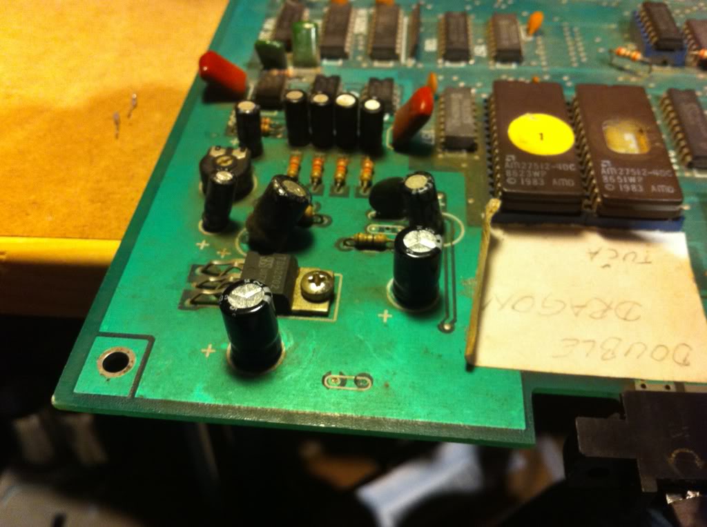
The board had some other obvious physical damages that needed fixing.
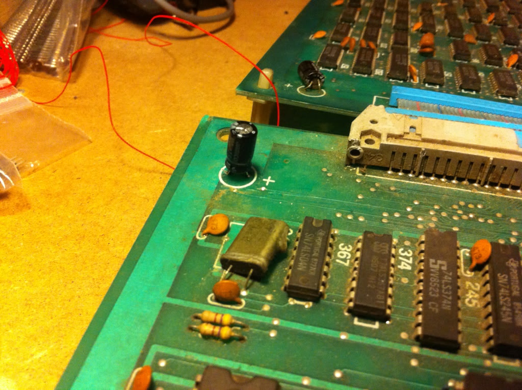
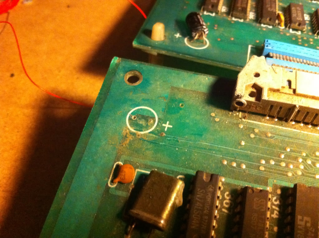
Here a knocked-off smoothening cap
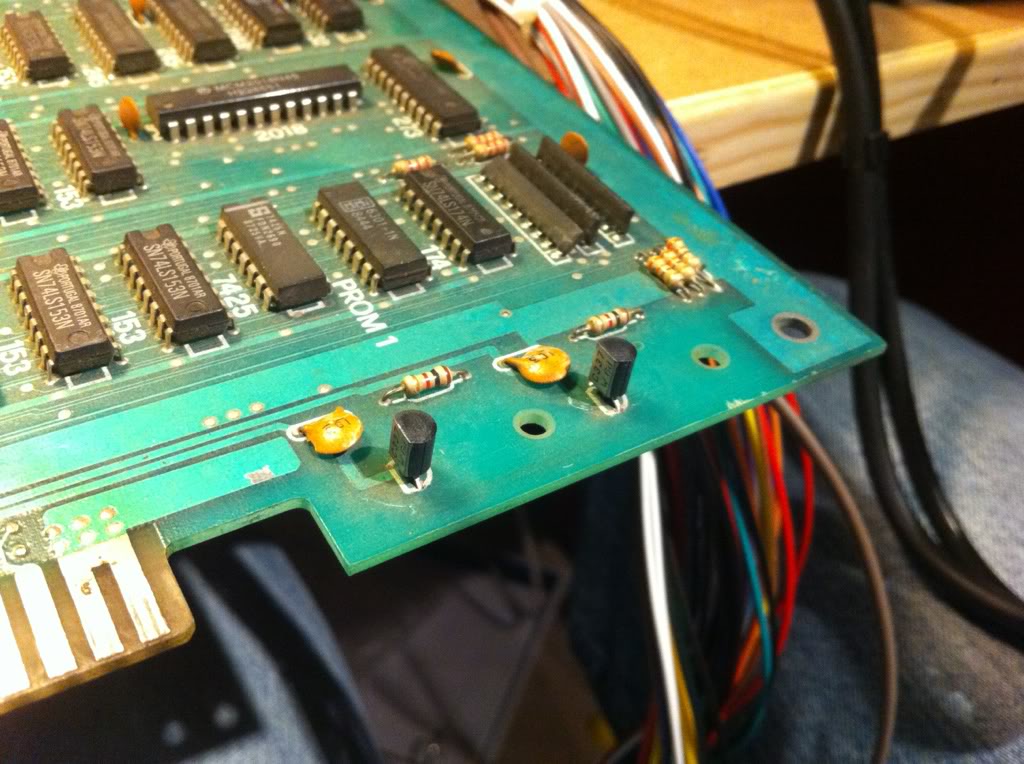
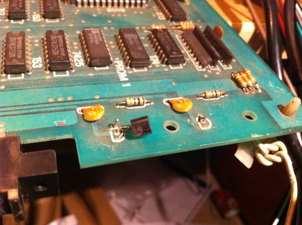
1 transistor with 2 pins ripped off and the other one missing all together
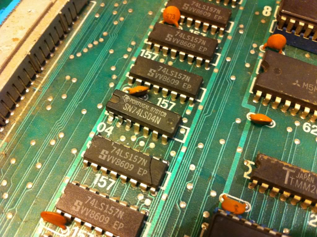
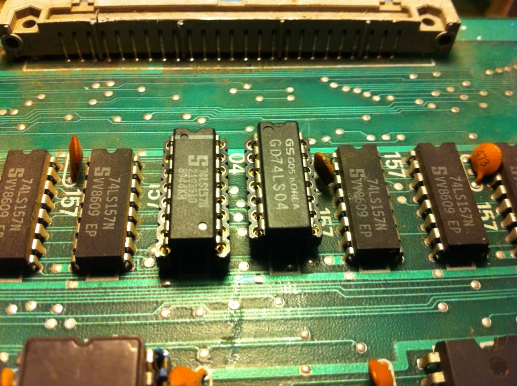
A physically broken 157; the 04 just beside it had also taken a big knock at some point and was replaced for good measure as well. Both spares was taken from scrap boards.
Now I did expect to see some kind of change when replacing the broken 157, but not the kind that I saw when hooking the board up again...
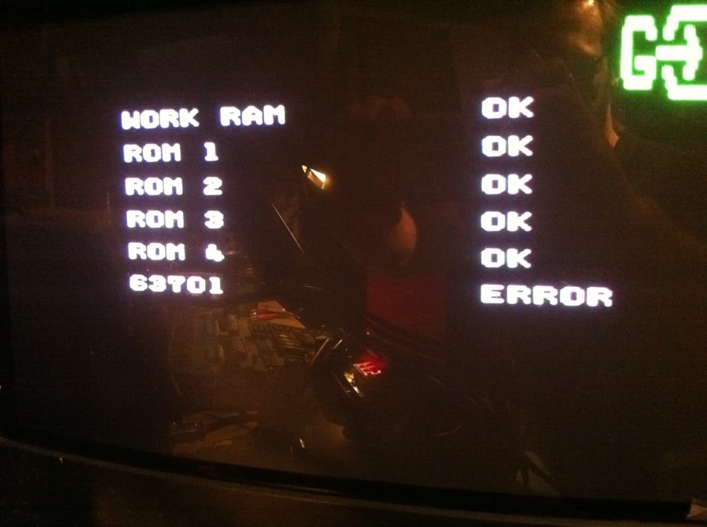
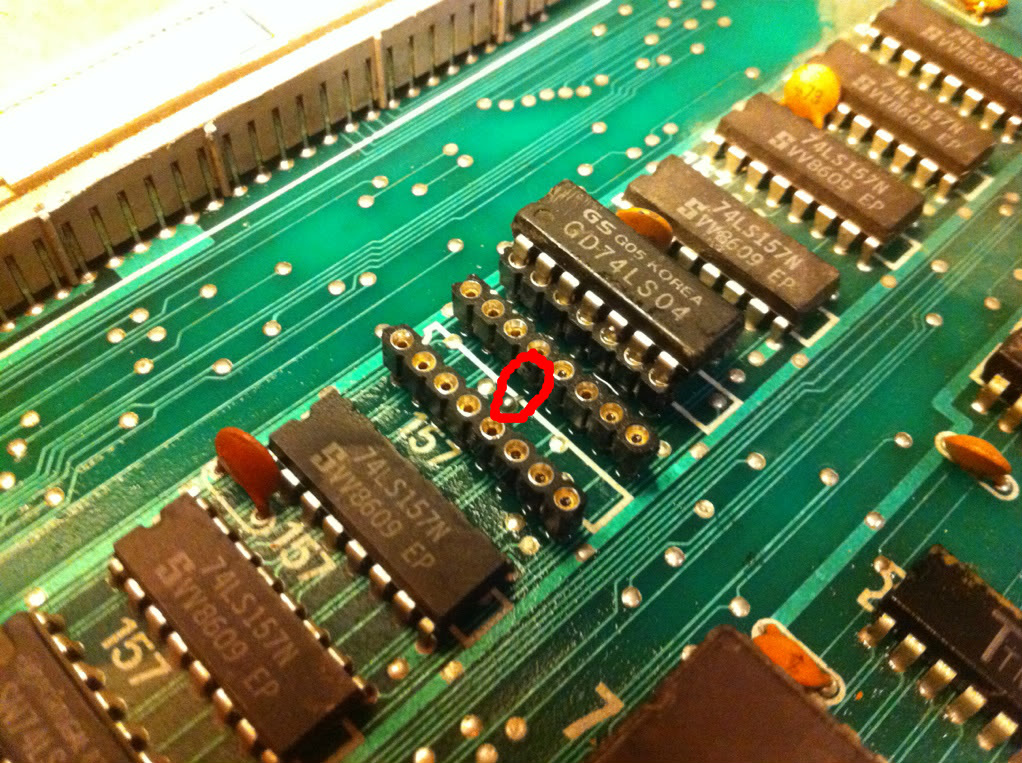
Hmmm, must have done something wrong when fitting them sockets. Pulled the 157 again and had a look. Now I really appreciated myself for always using breakable header sockets instead of normal sockets, as this gave my a clear look down between the two rows. I found one of the tracks between a via and one of the pins suspicious, and the continuity tester confirmed my hunch.
Patched it up with a little piece of kynar on the solderside.
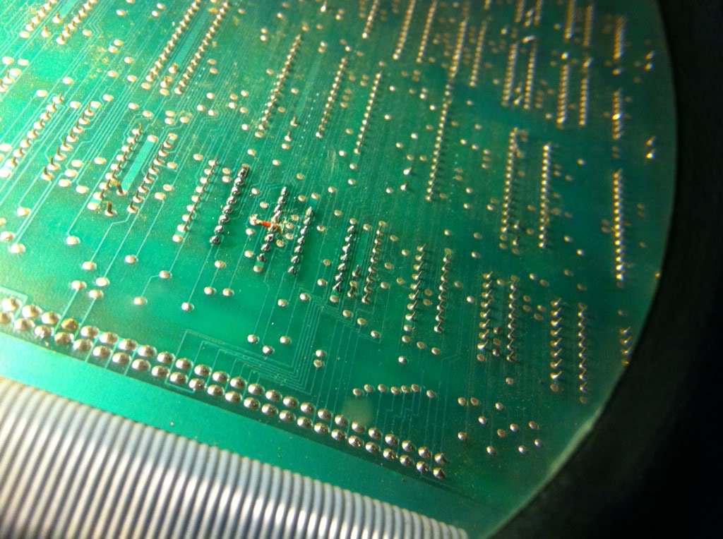
Now the boot error had gone, but there was still no change in regards to the graphics on screen.
Until now I had only concentrated on the primary PCB, so now I had a look at the secondary one. The component side looked incredibly fine, considering the damages found on the primary one. The solder side however had a fair among of scratches and was also pretty dirty.
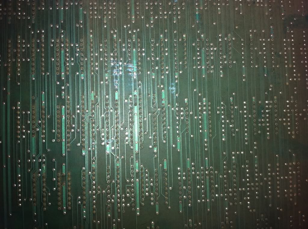
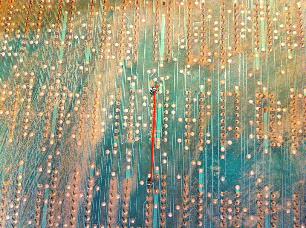
I gave the worst place a light scrup with rubbing alcohol and tooth brush, and I found 1 pin touching a nearby via and a track that was scratched in 3 places. Again the continuity tester confirmed...
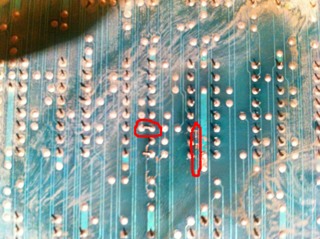
So straitened the pin (along with about 5 others that I found, for good measure) with a Stanley knife a alot of caution. Then patched the broken track with kynar.
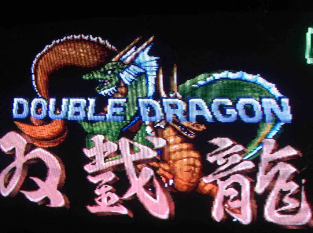
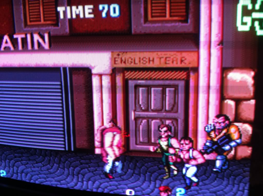
and the sprites where alive and kicking again };-)
(please take note of the cute up-skirt view you get in this pic };-P).
Now all was good, and I started test-playing the game. But when I tried a 2-player game, the hit-button for player-2 was unresponsive. A quick glance at the input section on the primary PCB, and my eyes caught this broken resistor array.
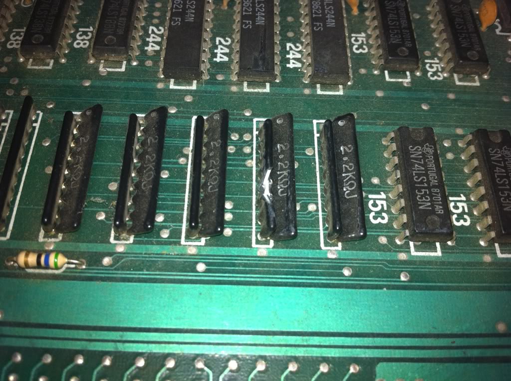
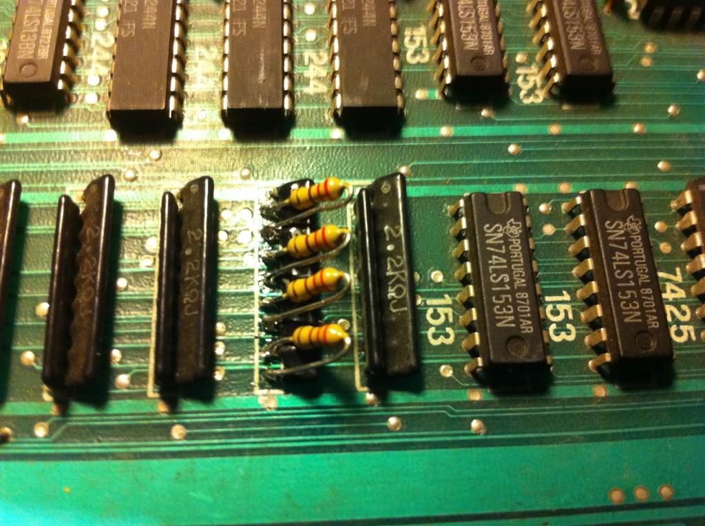
By measuring on one it's sisters, I found that this was not the same type as nomally used for pull-ups (with a common point). It was more like 4 parallel resistors just packed into one house. I couldn't find any of those on any of my scraps, so desided on just fitting 4 standard 220Ohms resistors. Now the original bootleggers had put 2 componentpins into each hole, but with the pin-diameter of the standard resistors, I had no chance of doing that. So I desoldered the standard pull-up array
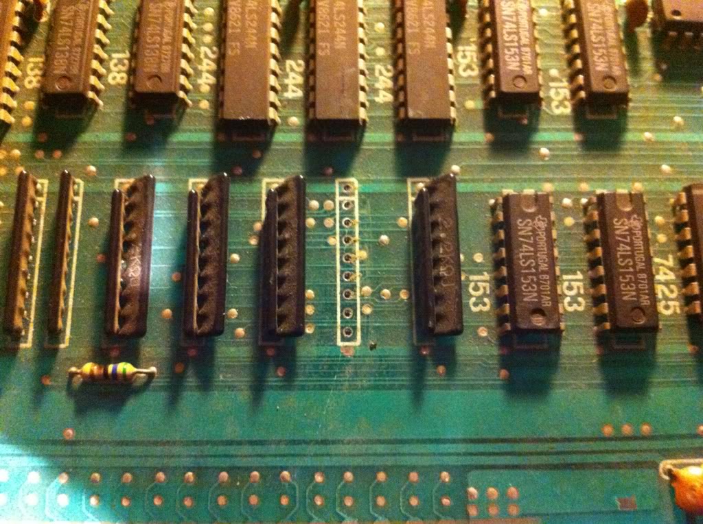
and resoldered it so that it was possible to access the pins from the component side. Then I soldered the 4 standard resistors directly on the pins from the component side.
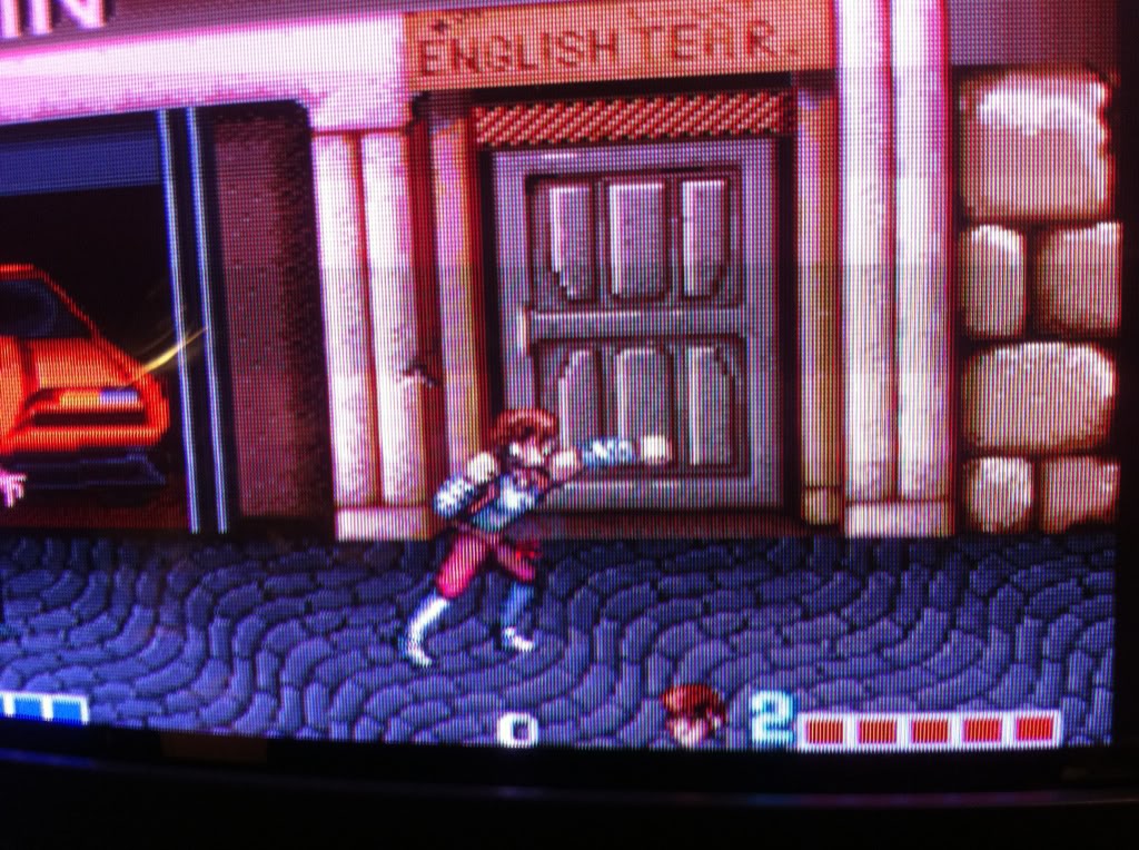
And once again our Red Hero is able to swing his pork chop against the baddies };-P
And finally this case is closed };-D
