Difference between revisions of "PCB Repair Logs Zaxxon"
(Created page with "==Zaxxon== <p><table class="infobox vevent" style="width:22em;" cellspacing="5"> <caption class="summary" style=""><b>Zaxxon</b></caption> <tr class="> <td colspan="2" class="...") |
m |
||
| Line 17: | Line 17: | ||
'''Repairer:''' [http://www.aussiearcade.com.au/member.php/1983-Womble Zaxxon]<br> | '''Repairer:''' [http://www.aussiearcade.com.au/member.php/1983-Womble Zaxxon]<br> | ||
'''Forum Thread:''' [http://www.aussiearcade.com.au/showthread.php/46961-Sega-Zaxxon-Repair-Log Zaxxon PCB Repair]<br> | '''Forum Thread:''' [http://www.aussiearcade.com.au/showthread.php/46961-Sega-Zaxxon-Repair-Log Zaxxon PCB Repair]<br> | ||
<br> | |||
Stu very kindly donated me a faulty Zaxxon board recently and even dropped it round for me, as it was an original and a classic I took pity on it. I had googled what the board was and had found the schematics but what arrived was not what I was expecting. All the doco and almost all the photos show a dual PCB stack, what I had was this... | |||
<br> | |||
<br> | |||
[[File:Pcb repair zaxxon 1.jpg]] | |||
<br> | |||
<br> | <br> | ||
... a three PCB stack with an unusual thin ribbon cable connecting the top board. It was in pretty good nick with a few nice original features, like the original Sega branded Z80 hidden away under the upper board... | |||
<br> | |||
<br> | |||
[[File:Pcb repair zaxxon 2.jpg]] | |||
<br> | |||
<br> | |||
...and some nice logos etched into the copper of the boards... | |||
<br> | |||
<br> | |||
[[File:Pcb repair zaxxon 3.jpg]] | |||
<br> | |||
<br> | |||
This board set appears to be the original early release of the game, with the documented dual PCB stack being the more common version. The boards were missing the rear screw mounts and the ones at the front of the board had had a very hard life, the bolts were bent, somewhat corroded and the metal feet were locked up solid. | |||
The upper board from first glances appeared to be entirely devoted to the audio... | |||
<br> | |||
<br> | |||
[[File:Pcb repair zaxxon 4.jpg]] | |||
<br> | |||
<br> | |||
... this game is before the era of dedicated sound chips so all the sound effects were produced with collections of 555 timers, strings of op-amps, electronically controlled switches and a rather chunky opto-isolator block. | |||
With the audio board out of the way I could get a better look at the main board... | |||
<br> | |||
<br> | |||
[[File:Pcb repair zaxxon 5.jpg]] | |||
<br> | |||
<br> | |||
...and the glorious gold plated Sega Z80 - have never seen one of these before! | |||
<br> | |||
<br> | |||
[[File:Pcb repair zaxxon 6.jpg]] | |||
<br> | |||
<br> | |||
The board also is fully decked out with 25 series EPROMs, all 2564s except for a single 2532. The 25 series was a very short lived standard produced be by Texas Instruments, they were in direct competition with Intel's 27 Series chips that became the standard and are seen on virtually every arcade board from the late 70s to the end of the 90s. The pinouts are very slightly different, enough to make them unreadable on many eprom readers, mine included, as the /OE is the wrong place. So I couldn't dump the ROMs and as the ROM windows had been completely exposed to light since 1982 I was not hugely convinced they would contain useful data. Although the ROM cases have the raised surface round the window and the ROM labels are on the lower outer surface it meant all the original Sega labels are in mint condition too which is insane for a board this old. | |||
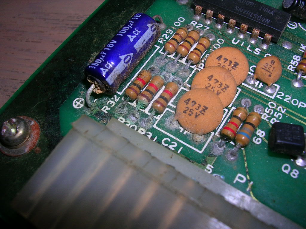
The only sign of damage was that one of the 100uF 16v axial electrolytic capacitors had leaked its guts over one corner of the board and corroded some of the components and tracks, it looks nasty but is still fine. | |||
<br> | |||
<br> | |||
[[File:Pcb repair zaxxon 7.jpg]] | |||
<br> | |||
<br> | |||
Someone had done some troubleshooting on the audio board and had cut some tracks only to join them up with bits of wire and splodges of solder at some stage in the past. It's a fairly brutal method of troubleshooting which allows you isolate parts of the board without desoldering chips, am not a fan of it myself but you do see it. | |||
The solder side of the lower board was also in mint condition, barely a mark on it, but as I couldn't shift the screw mounts between the two main boards I couldn't get them apart to see what was on the component side so gave up on the inspection stage and moved onto making up the harness to see what it actually did. | |||
As this board is not the one mentioned in all the documentation I was pretty cautious to confirm if the pinouts were going to match. The 5v and ground lines are easy to track down as any 74 series TTL chip on the board will give you a known pin for each and you can buzz it back to the edge connector easily enough. What was less easy to confirm was the -5v and the 12v rails shown on the pinouts. Normally the 12v line is solely used by the amp chip, but it was clear there was no connectivity between the audio board and the lower two main boards on any of the voltage lines so there was no connectivity from the edge connector to the amp chip, but the 12v line was still plumbed in. The two main boards have a linker cable between then that carries the 5V, ground and what should be the -5v and the 12v from the CPU board (the one with the edge connector) to the lower video board. Digging through the schematics for the later revision of the board I could see that 12V was required by the video generation circuit which uses it to derive a 6v feed for some analogue sections of the board, and much the same for the -5V so I was pretty confident the pinout was correct, at least for the power lines. As for the video out it didn't really matter if I got that wrong as the only result would be a lack of video, rather than a smoking wreck if I had got the power lines wrong. | |||
The audio board 5v, 12v and ground lines ran back to a very tatty 6 pin connector that had some tatty old wire soldered directly to it, wires that had clearly been there for decades so I powered up the main board stack without the audio board present and was met by this... | |||
<br> | |||
<br> | |||
[[File:Pcb repair zaxxon 8.jpg]] | |||
<br> | |||
<br> | |||
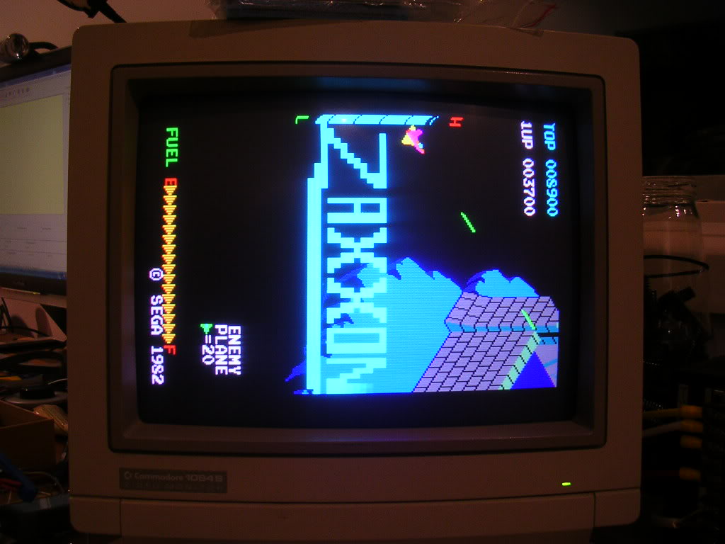
... and no smoke or any hot chips, a good sign that the video generation side of the board was working fine and that the power lines were correct, clearly the main CPU was not running, or it was crashing very early on. So a quick reseat of the ribbon cables and the socketed chips I could get to on the upper board and the game fired right up. | |||
<br> | |||
<br> | |||
[[File:Pcb repair zaxxon 9.jpg]] | |||
<br> | |||
<br> | |||
[[File:Pcb repair zaxxon 10.jpg]] | |||
<br> | |||
<br> | |||
Time for some audio! First thing to do was to get the crappy old stumps off wire off the connector... | |||
<br> | |||
<br> | |||
[[File:Pcb repair zaxxon 11.jpg]] | |||
<br> | |||
<br> | |||
... clearly the work of a skilled craftsman! | |||
Normally I try to save connectors but this was in pretty bad shape and the pins were cylindrical whereas square cut pins are the standard these days. | |||
<br> | |||
<br> | |||
[[File:Pcb repair zaxxon 12.jpg]] | |||
<br> | |||
<br> | |||
The chances of finding an original mate for this was next to zero and a modern equivalent would not make a great contact on the old style pins, so off it came... | |||
<br> | |||
<br> | |||
[[File:Pcb repair zaxxon 13.jpg]] | |||
<br> | |||
<br> | |||
... and a new one from Jaycar went on. | |||
<br> | |||
<br> | |||
[[File:Pcb repair zaxxon 14.jpg]] | |||
<br> | |||
<br> | |||
I also picked up the equivalent mate for the harness extension cable I had to make. and buzzed through the pinout, this connector takes 5V, 12V ground and provides the two speaker outputs. | |||
Pin 1 is labelled in the etching on the board and this pinout is this. | |||
1 = 12V | |||
2 = 5V | |||
3 = Speaker + | |||
4 = Speaker + | |||
5 = Not connected | |||
6 = Ground | |||
This is the only difference in the pinout for the early board variant over the later dual board set up, the speakers do not connect via the edge connector. | |||
So with the additional power and audio lines fed back to the harness... | |||
<br> | |||
<br> | |||
[[File:Pcb repair zaxxon 15.jpg]] | |||
<br> | |||
<br> | |||
...I flicked the switch and got this awful racket. | |||
<br> | |||
<br> | |||
{{#ev:youtube|DFGEUreK6oA}} | |||
<br> | |||
<br> | |||
The explosion sound does play when the test button is pressed so it was clear that some of the sound system was working, and possibly this was just a problem with the amplifier. The usual suspects in old amps are electrolytic caps so I went over the sound board with the ESR meter, but found only one was bad - C60 a 2.2uF 50V which was giving an ESR reading of 85 ohms instead of the 2.5 that all the others of that rating gave. So I replaced it with a new one and fired the board back up, only to get the exact same fault again. | |||
After some more poking around I couldn't find anything particularly wrong other than the obviously bodgy signs the board had been worked on before, possibly the result of someone else trying to troubleshoot this fault, certainly nothing had actually been replaced on the board so its likely they gave up on it. Multiple caps had been removed but they had all been put back as the make and design was consistent across the board, one of the 555 timers showed signs that something had been soldered to its pin 1 at some stage, and the amp chip had been desoldered and reinstalled. | |||
<br> | |||
<br> | |||
[[File:Pcb repair zaxxon 16.jpg]] | |||
<br> | |||
<br> | |||
There was also the cut and bridged tracks... | |||
<br> | |||
<br> | |||
[[File:Pcb repair zaxxon 17.jpg]] | |||
<br> | |||
<br> | |||
...ugly but electrically sound. | |||
To rule out the amplifier chip I needed to feed its input signal into an external amplifier, but as the volume pot on this board shorts the audio signal hard to ground when it is fully turned down I needed to test with the volume up or there was no signal left to export. So as the soldering on the amp chip was not very good I took it off the board... | |||
<br> | |||
<br> | |||
[[File:Pcb repair zaxxon 18.jpg]] | |||
<br> | |||
<br> | |||
... and fed the signal via some test clips into my PC speakers, and got the exact same noise. This proved the amp chip was not part of the problem. Having seen that last picture I ended up in the garden with a paintbrush getting all the dust and crap off these board too, clouds of dust everywhere. | |||
At this stage I decided it was possible that the honking great loop of wire the previous repairer had used to bridge one of his cut tracks was picking up interference from the lower board. I have seen a similar issue before on a Golden Axe PCB where a repairer had used about a yard of wire to bridge a small gap and it was causing the graphics to glitch like crazy, presumably by collecting interference as it travelled from A to B past all the other highly active areas of the board. | |||
<br> | |||
<br> | |||
[[File:Pcb repair zaxxon 19.jpg]] | |||
<br> | |||
<br> | |||
The blue wire is the wire that was originally on the board, the black wire lying flush along the original track line is my replacement, it is chunky as the track it is bridging its pretty hefty. The alternative was to scratch away at the lacquer to get back to copper and then solder some metal component legs across the break, but as the break was rather messy it was easier to bridge past it to the nearest points that were easy to solder too. With that fix complete and the amp back on the board I fired it up again. The impression of a 2 stroke engine on its last legs was gone, unfortunately the fairly constant roaring noise was still present. The only other potential cause of interference that I could see was the loss of the axial electrolytic that had burst on the main board. As the board supports were rusted, or bent solid, and the bolt heads were badly chewed... | |||
<br> | |||
<br> | |||
[[File:Pcb repair zaxxon 20.jpg]] | |||
<br> | |||
<br> | |||
... my only option was drill the bolt head off... | |||
<br> | |||
<br> | |||
[[File:Pcb repair zaxxon 21.jpg]] | |||
<br> | |||
<br> | |||
...while taking care not to let the metal shards get into the board. | |||
With the boards finally separated the lower board was revealed... | |||
<br> | |||
<br> | |||
[[File:Pcb repair zaxxon 22.jpg]] | |||
<br> | |||
<br> | |||
and the crappy axial... | |||
<br> | |||
<br> | |||
[[File:Pcb repair zaxxon 23.jpg]] | |||
<br> | |||
<br> | |||
...was replaced with a 35v 100uF axial from a scrap board. | |||
Reconnecting everything once more and powering it up I was greeted with silence, well a faint his from the speaker and a glorious explosion when I pressed the test button, all the interference was gone. | |||
I had hoped that was the end of it but some of the sound effects were not right, there are three explosions in the game, one massive one which is the one you hear when you trigger test mode, which I think is the "killing the end of level robot" explosion. There is also the ship explosion when you die and the missile explosion which are smaller shorter effects. These were just a very faint whisper of what they should be, almost a hiss. | |||
Having ruled out the amp chip, and all the caps on the board I had to dive into the actual noise generation circuitry which is not something I have done before. On later boards there are usually audio generator chips that are either good or bad whereas this was a tangle of timers, op-amps, resistors and capacitors, pretty much the guts of a later sound chip laid out with individual parts. | |||
Time for the schematic, even tho it was for a different board layout and the component IDs and locations made no sense it was likely that the actual circuit was the same, what was useful was that it showed how the sounds are actually triggered. The ribbon cable feeds an 8 bit bus, 2 data lines, and a couple of control lines to an 8255 chip which is a parallel peripheral interface chip. All this chip is doing is pulling low lines on the audio board that trigger the sound generator sections of the circuit, and as these were labelled with the sound effect name I was able to trigger them individually myself by running the board with the 8255 unplugged and connecting the relevant output pins on the empty 8255 socket to ground, which is what the 8255 would do anyway under the direction of the main board. Pretty handy as in the game so many sounds occur at once it is hard to spot which one is having issues. | |||
<br> | |||
<br> | |||
[[File:Pcb repair zaxxon 24.jpg]] | |||
<br> | |||
<br> | |||
So, armed with a de-soldering iron cleaning poker clipped that was connected to system ground I could do this... | |||
<br> | |||
<br> | |||
{{#ev:youtube|r0V92-FUQxw}} | |||
<br> | |||
<br> | |||
Only the ship explosion and the missile explosion are wrong, so time for more schematic diving. This time I had to print out the four A4 pages of the manual that had the audio schamtics as I had to work in from the s-exp and the m-exp trigger lines and follow the circuit path through to the output line that connects to the amplifier. | |||
It was more likely that it was a single fault that was causing both issues so I needed to know where the common circuitry for these two sounds was. It seems that there were a couple of 555 timer based white noise generators on the board that were constantly running, producing signals called "Noise 1" and "Noise 2", and the schematic suggests that these were the component parts of the explosion sound effects. As one of the explosion sounds on this board was still healthy, and also because I could see the related 555 timers buzzing away I was fairly sure that section was still fine. So the fault was more likely to be downstream of the "noise 1 and 2" sections of the board, somewhere in the tangle of Op-Amps. On the schematics these two sound effects take different paths through different chips, but after half an hour of tracing and updating the chip locations on the diagram to match this board it became clear that on this layout the paths are common at this point... | |||
<br> | |||
<br> | |||
[[File:Pcb repair zaxxon 25.jpg]] | |||
<br> | |||
<br> | |||
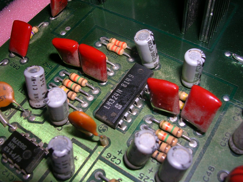
... through 4 op-amps and a two MB4391s. The MB4391s are actually Sega chips on this board and although MB4391 does seem to excite the datasheet mining websites none of them had any info on what these actually are. The four op-amps (the triangle symbols) on the diagram above all resided on a single quad op-amp chip, an LM324 at IC13 on this board. | |||
<br> | |||
<br> | |||
[[File:Pcb repair zaxxon 26.jpg]] | |||
<br> | |||
<br> | |||
At this point the fault was coming and going, sometimes it was a faint hiss, other times it was only slightly distorted, but I found I could sometimes annoy the fault by touching the pins of this op-amp. When it was very faint and hissy I had no effect, when it was almost correct I could cause it to fail about 50% of the time. I could also confirm that touching the Sega upstream chip and the associated passive components had no effect at all. So I went mining in my scrap box and found and LM324 on an old bootleg board. When the original one was replaced I was hopeful this would be the final cure - it wasn't. The ship explosion was totally missing and the missile explosion was even more distorted, clearly this was a bad LM324 too. | |||
So another lunchtime walk to to jaycar, and I was $2 lighter and this beauty ended up on the board. | |||
<br> | |||
<br> | |||
[[File:Pcb repair zaxxon 27.jpg]] | |||
<br> | |||
<br> | |||
I resorted to a socket here because I didn't want to risk having to take this off the board again to troubleshoot further as there are only so many times a PCB will survive the heat cycle, plus with a socket you can bend pins out of the way to disconnect parts of a chip which can be pretty useful. | |||
Thankfully it wasn't an issue because this new LM324 completely fixed the two explosion effects. | |||
All that remains now is to refit the board supports, install new ones to replace the knackered ones and shrink the heatsink on the harness! | |||
Job done! | |||
<br> | <br> | ||
<br>[[PCB_Repair_Index|Back to PCB Repair Index]] | <br>[[PCB_Repair_Index|Back to PCB Repair Index]] | ||
Revision as of 14:15, 5 September 2012
Zaxxon
| PCB Image | Reserved |
|---|---|
| Pin Out | Reserved |
Repairer: Zaxxon
Forum Thread: Zaxxon PCB Repair
Stu very kindly donated me a faulty Zaxxon board recently and even dropped it round for me, as it was an original and a classic I took pity on it. I had googled what the board was and had found the schematics but what arrived was not what I was expecting. All the doco and almost all the photos show a dual PCB stack, what I had was this...
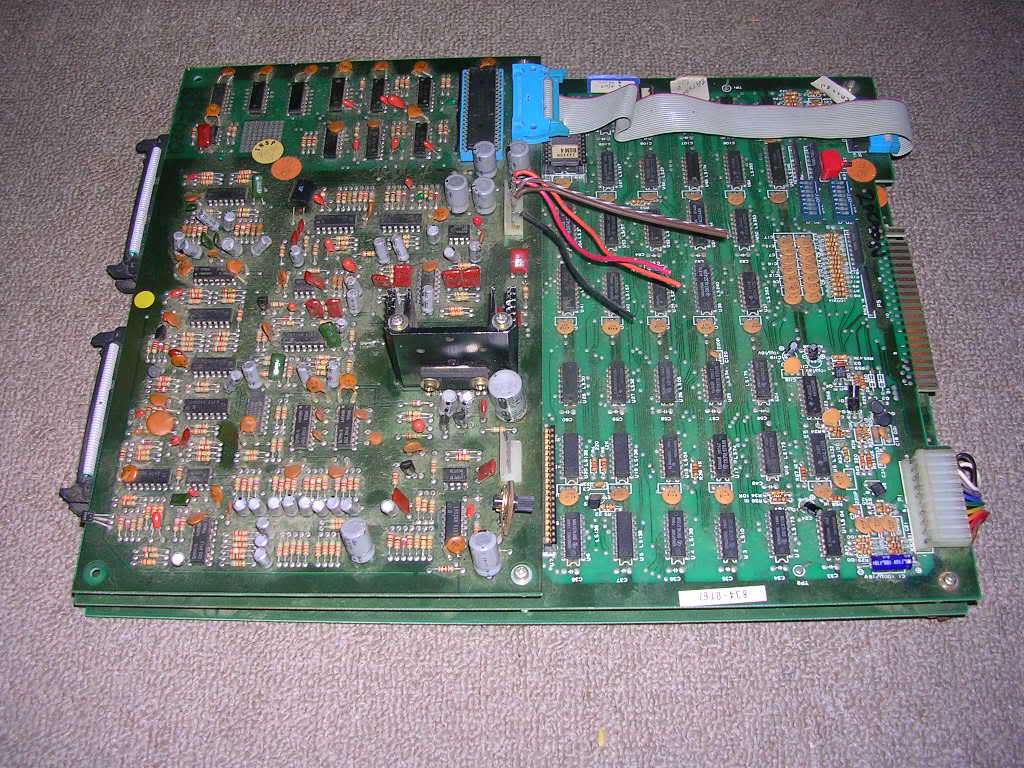
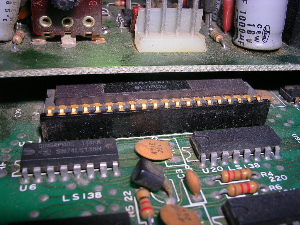
... a three PCB stack with an unusual thin ribbon cable connecting the top board. It was in pretty good nick with a few nice original features, like the original Sega branded Z80 hidden away under the upper board...
...and some nice logos etched into the copper of the boards...
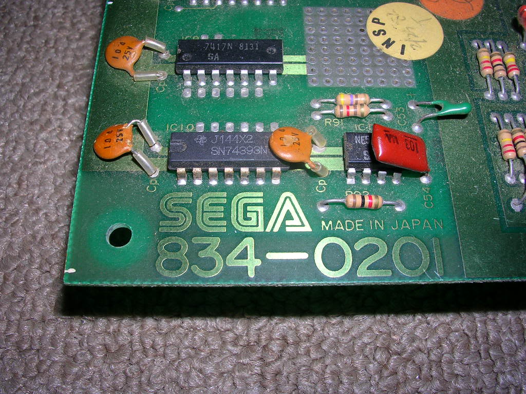
This board set appears to be the original early release of the game, with the documented dual PCB stack being the more common version. The boards were missing the rear screw mounts and the ones at the front of the board had had a very hard life, the bolts were bent, somewhat corroded and the metal feet were locked up solid.
The upper board from first glances appeared to be entirely devoted to the audio...
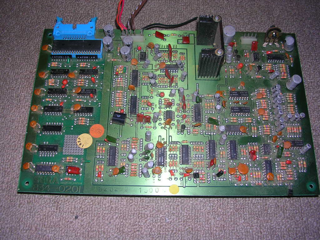
... this game is before the era of dedicated sound chips so all the sound effects were produced with collections of 555 timers, strings of op-amps, electronically controlled switches and a rather chunky opto-isolator block.
With the audio board out of the way I could get a better look at the main board...
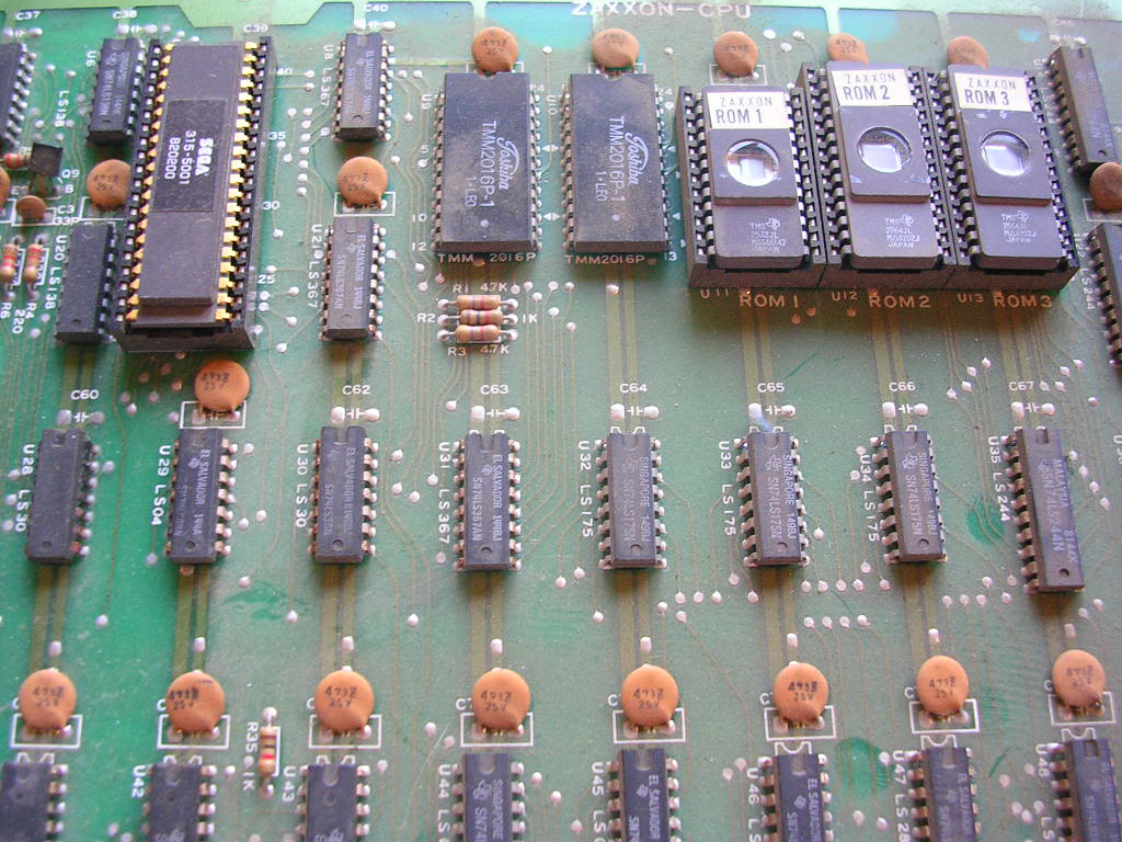
...and the glorious gold plated Sega Z80 - have never seen one of these before!
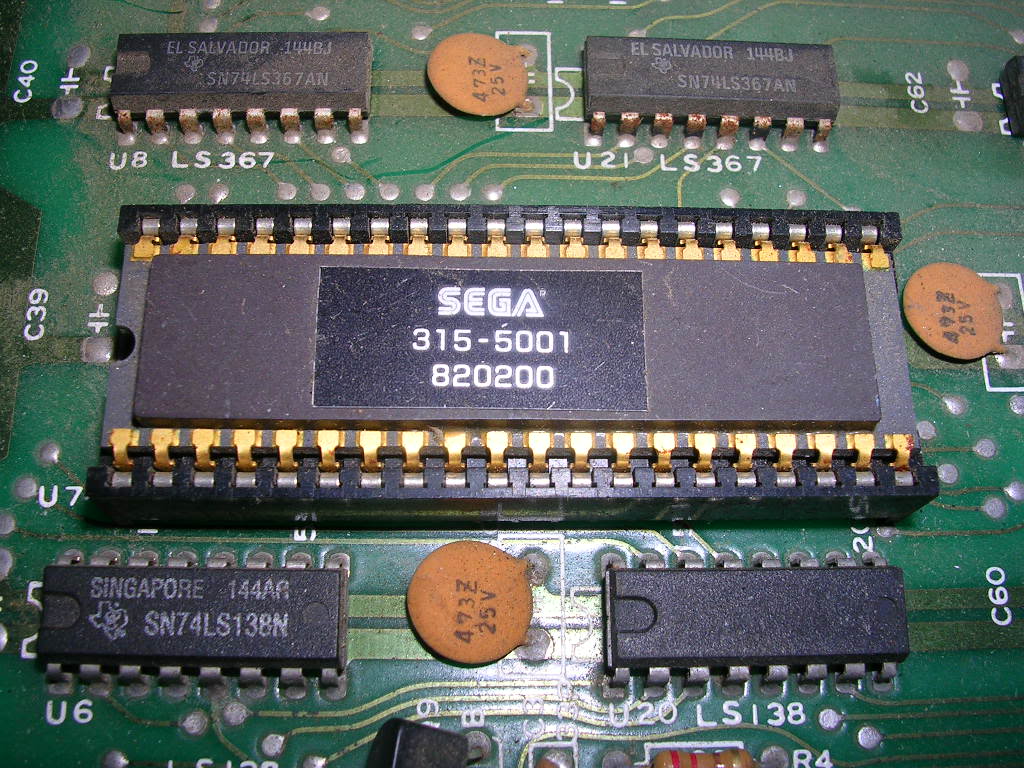
The board also is fully decked out with 25 series EPROMs, all 2564s except for a single 2532. The 25 series was a very short lived standard produced be by Texas Instruments, they were in direct competition with Intel's 27 Series chips that became the standard and are seen on virtually every arcade board from the late 70s to the end of the 90s. The pinouts are very slightly different, enough to make them unreadable on many eprom readers, mine included, as the /OE is the wrong place. So I couldn't dump the ROMs and as the ROM windows had been completely exposed to light since 1982 I was not hugely convinced they would contain useful data. Although the ROM cases have the raised surface round the window and the ROM labels are on the lower outer surface it meant all the original Sega labels are in mint condition too which is insane for a board this old.
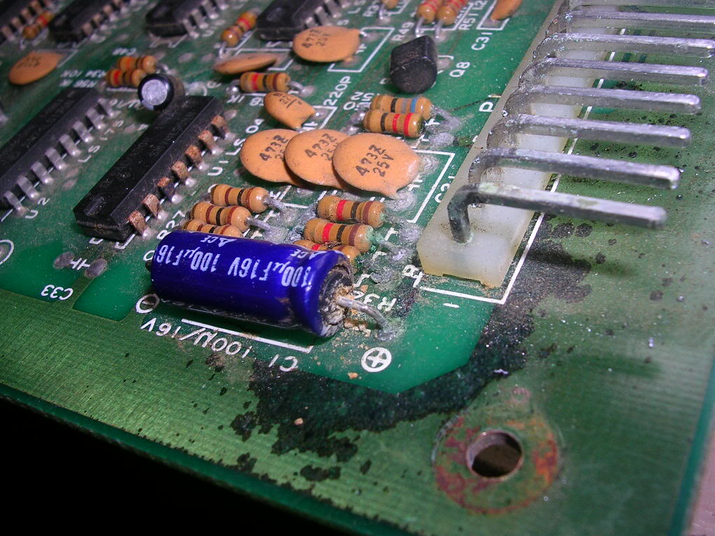
The only sign of damage was that one of the 100uF 16v axial electrolytic capacitors had leaked its guts over one corner of the board and corroded some of the components and tracks, it looks nasty but is still fine.
Someone had done some troubleshooting on the audio board and had cut some tracks only to join them up with bits of wire and splodges of solder at some stage in the past. It's a fairly brutal method of troubleshooting which allows you isolate parts of the board without desoldering chips, am not a fan of it myself but you do see it.
The solder side of the lower board was also in mint condition, barely a mark on it, but as I couldn't shift the screw mounts between the two main boards I couldn't get them apart to see what was on the component side so gave up on the inspection stage and moved onto making up the harness to see what it actually did.
As this board is not the one mentioned in all the documentation I was pretty cautious to confirm if the pinouts were going to match. The 5v and ground lines are easy to track down as any 74 series TTL chip on the board will give you a known pin for each and you can buzz it back to the edge connector easily enough. What was less easy to confirm was the -5v and the 12v rails shown on the pinouts. Normally the 12v line is solely used by the amp chip, but it was clear there was no connectivity between the audio board and the lower two main boards on any of the voltage lines so there was no connectivity from the edge connector to the amp chip, but the 12v line was still plumbed in. The two main boards have a linker cable between then that carries the 5V, ground and what should be the -5v and the 12v from the CPU board (the one with the edge connector) to the lower video board. Digging through the schematics for the later revision of the board I could see that 12V was required by the video generation circuit which uses it to derive a 6v feed for some analogue sections of the board, and much the same for the -5V so I was pretty confident the pinout was correct, at least for the power lines. As for the video out it didn't really matter if I got that wrong as the only result would be a lack of video, rather than a smoking wreck if I had got the power lines wrong.
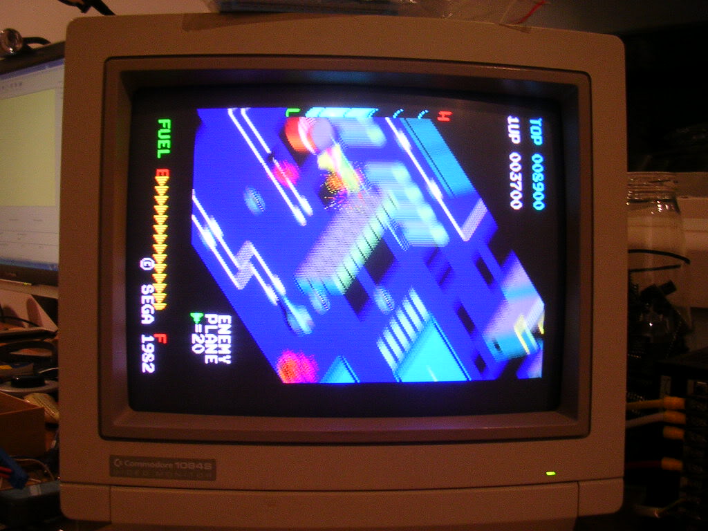
The audio board 5v, 12v and ground lines ran back to a very tatty 6 pin connector that had some tatty old wire soldered directly to it, wires that had clearly been there for decades so I powered up the main board stack without the audio board present and was met by this...
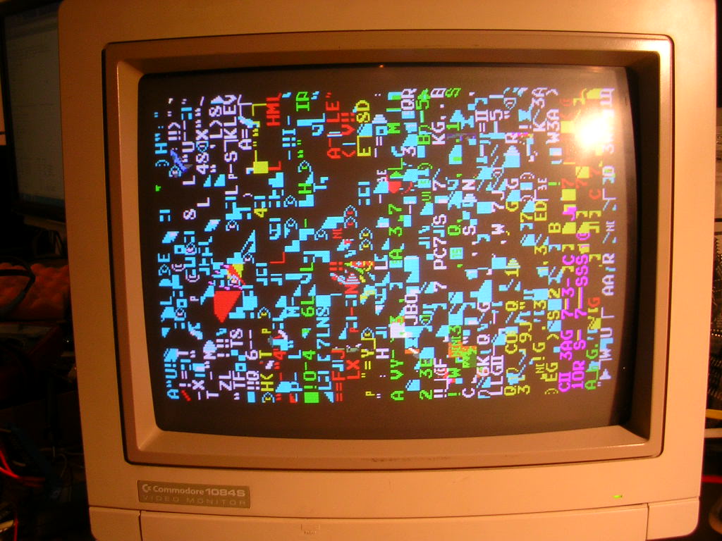
... and no smoke or any hot chips, a good sign that the video generation side of the board was working fine and that the power lines were correct, clearly the main CPU was not running, or it was crashing very early on. So a quick reseat of the ribbon cables and the socketed chips I could get to on the upper board and the game fired right up.
Time for some audio! First thing to do was to get the crappy old stumps off wire off the connector...
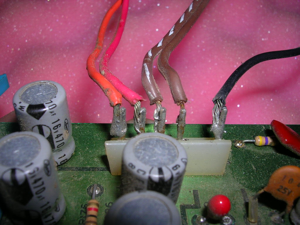
... clearly the work of a skilled craftsman!
Normally I try to save connectors but this was in pretty bad shape and the pins were cylindrical whereas square cut pins are the standard these days.
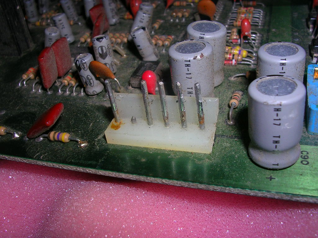
The chances of finding an original mate for this was next to zero and a modern equivalent would not make a great contact on the old style pins, so off it came...
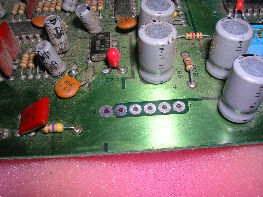
... and a new one from Jaycar went on.
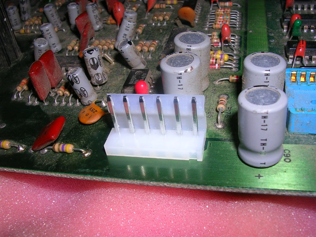
I also picked up the equivalent mate for the harness extension cable I had to make. and buzzed through the pinout, this connector takes 5V, 12V ground and provides the two speaker outputs.
Pin 1 is labelled in the etching on the board and this pinout is this.
1 = 12V 2 = 5V 3 = Speaker + 4 = Speaker + 5 = Not connected 6 = Ground
This is the only difference in the pinout for the early board variant over the later dual board set up, the speakers do not connect via the edge connector.
So with the additional power and audio lines fed back to the harness...
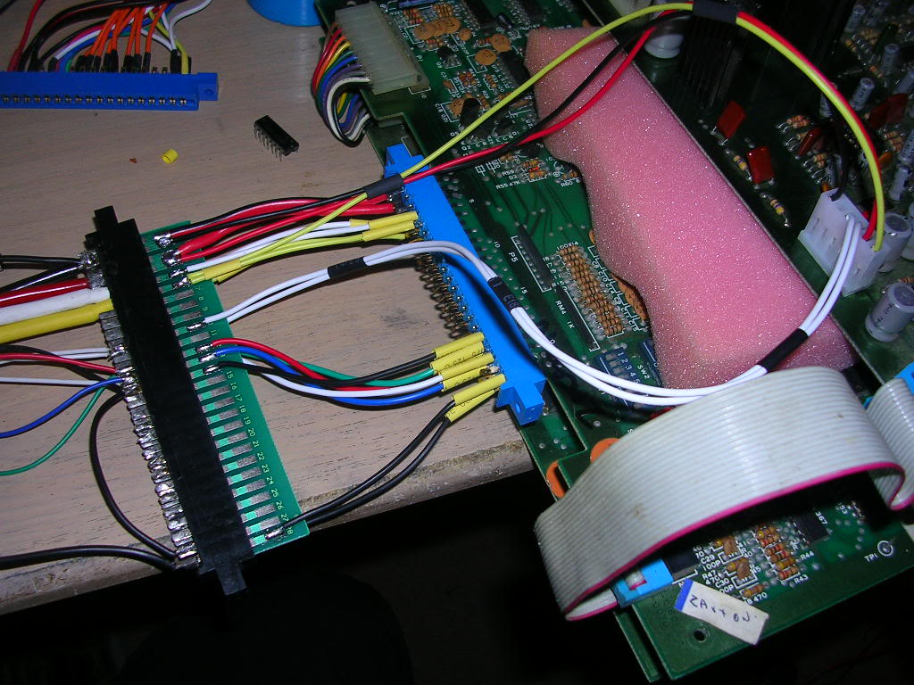
...I flicked the switch and got this awful racket.
The explosion sound does play when the test button is pressed so it was clear that some of the sound system was working, and possibly this was just a problem with the amplifier. The usual suspects in old amps are electrolytic caps so I went over the sound board with the ESR meter, but found only one was bad - C60 a 2.2uF 50V which was giving an ESR reading of 85 ohms instead of the 2.5 that all the others of that rating gave. So I replaced it with a new one and fired the board back up, only to get the exact same fault again.
After some more poking around I couldn't find anything particularly wrong other than the obviously bodgy signs the board had been worked on before, possibly the result of someone else trying to troubleshoot this fault, certainly nothing had actually been replaced on the board so its likely they gave up on it. Multiple caps had been removed but they had all been put back as the make and design was consistent across the board, one of the 555 timers showed signs that something had been soldered to its pin 1 at some stage, and the amp chip had been desoldered and reinstalled.
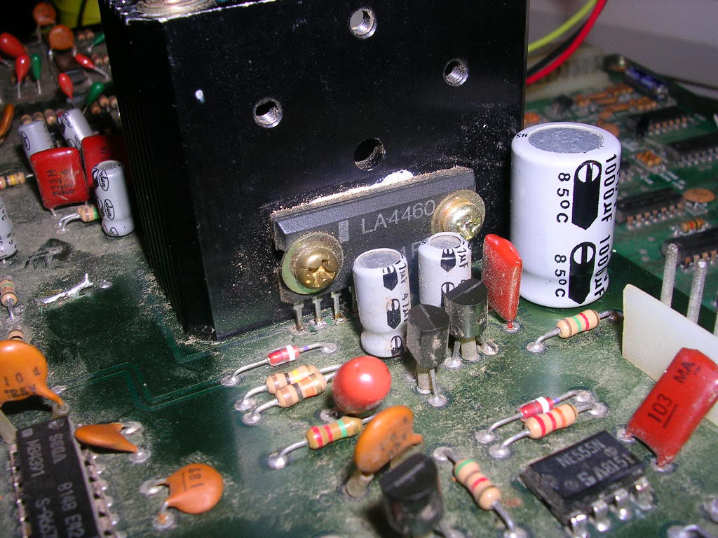
There was also the cut and bridged tracks...
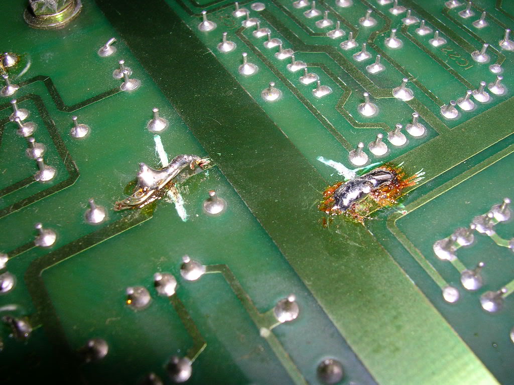
...ugly but electrically sound.
To rule out the amplifier chip I needed to feed its input signal into an external amplifier, but as the volume pot on this board shorts the audio signal hard to ground when it is fully turned down I needed to test with the volume up or there was no signal left to export. So as the soldering on the amp chip was not very good I took it off the board...
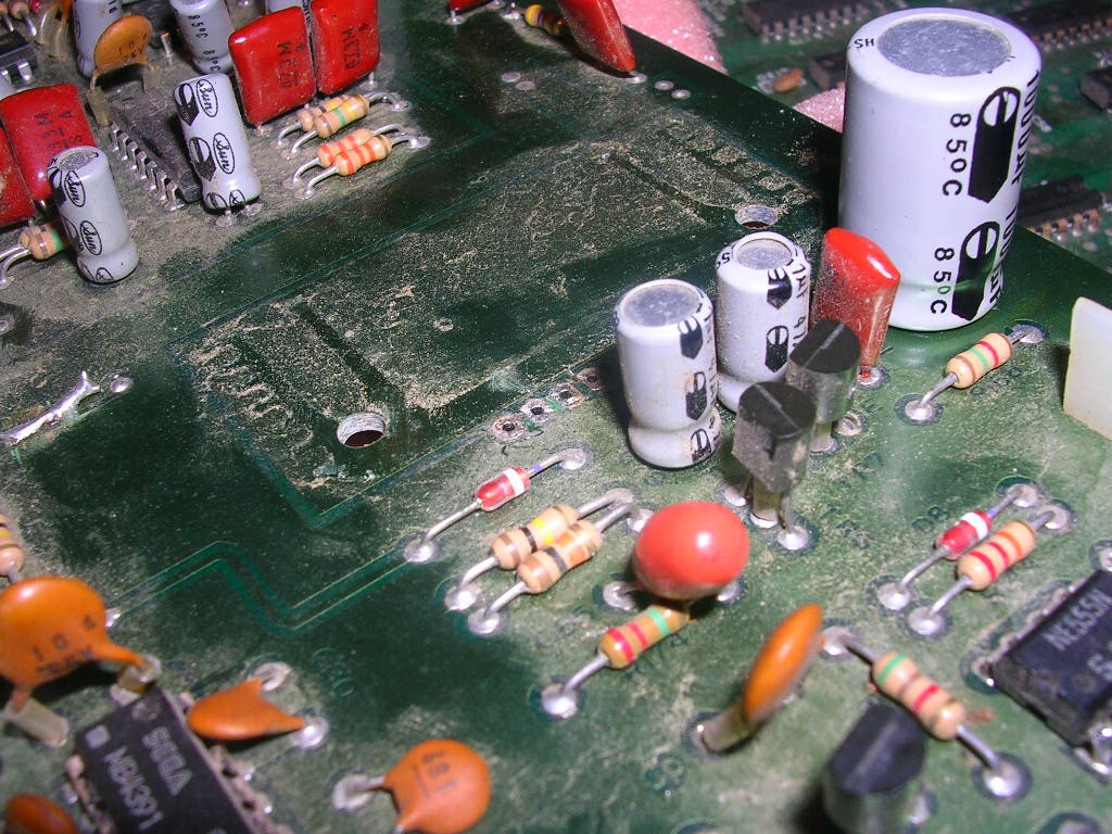
... and fed the signal via some test clips into my PC speakers, and got the exact same noise. This proved the amp chip was not part of the problem. Having seen that last picture I ended up in the garden with a paintbrush getting all the dust and crap off these board too, clouds of dust everywhere.
At this stage I decided it was possible that the honking great loop of wire the previous repairer had used to bridge one of his cut tracks was picking up interference from the lower board. I have seen a similar issue before on a Golden Axe PCB where a repairer had used about a yard of wire to bridge a small gap and it was causing the graphics to glitch like crazy, presumably by collecting interference as it travelled from A to B past all the other highly active areas of the board.
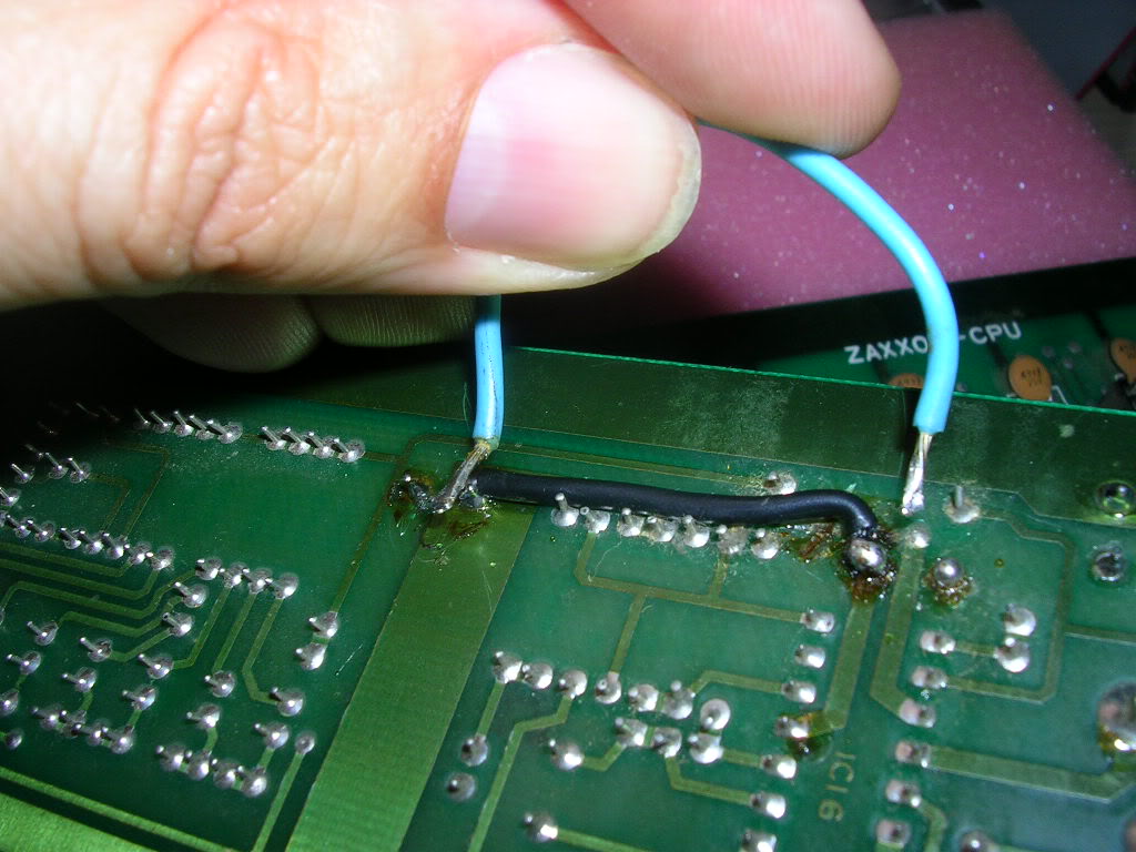
The blue wire is the wire that was originally on the board, the black wire lying flush along the original track line is my replacement, it is chunky as the track it is bridging its pretty hefty. The alternative was to scratch away at the lacquer to get back to copper and then solder some metal component legs across the break, but as the break was rather messy it was easier to bridge past it to the nearest points that were easy to solder too. With that fix complete and the amp back on the board I fired it up again. The impression of a 2 stroke engine on its last legs was gone, unfortunately the fairly constant roaring noise was still present. The only other potential cause of interference that I could see was the loss of the axial electrolytic that had burst on the main board. As the board supports were rusted, or bent solid, and the bolt heads were badly chewed...
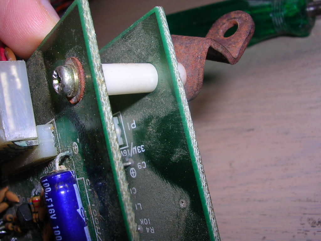
... my only option was drill the bolt head off...
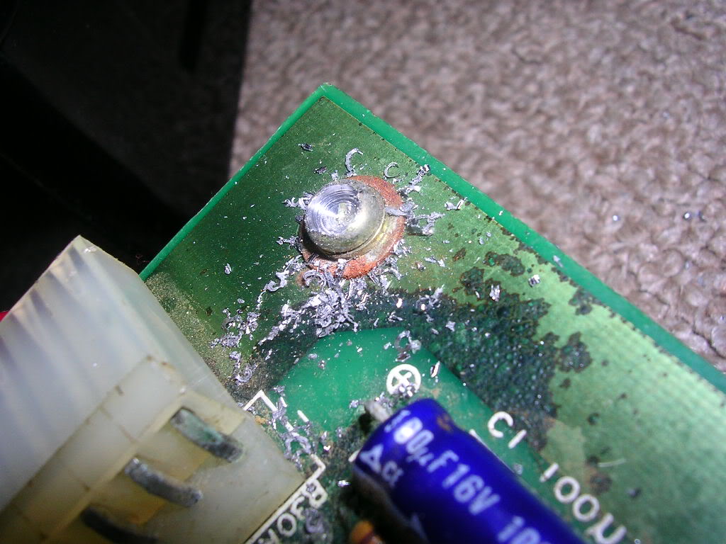
...while taking care not to let the metal shards get into the board.
With the boards finally separated the lower board was revealed...
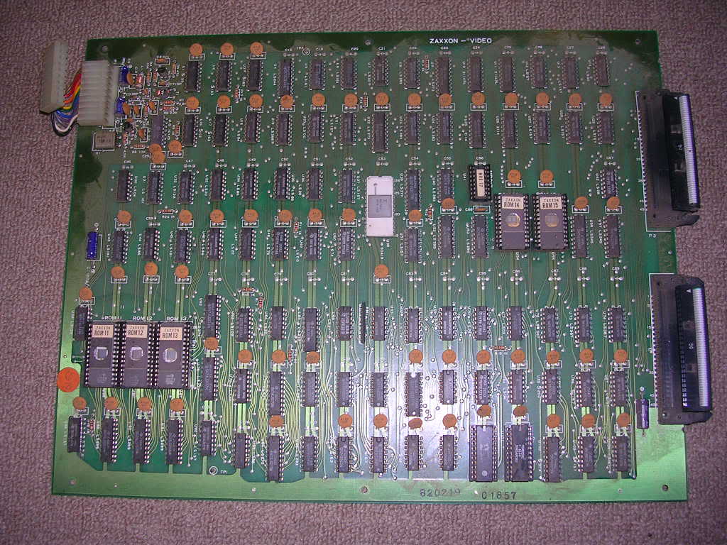
...was replaced with a 35v 100uF axial from a scrap board.
Reconnecting everything once more and powering it up I was greeted with silence, well a faint his from the speaker and a glorious explosion when I pressed the test button, all the interference was gone.
I had hoped that was the end of it but some of the sound effects were not right, there are three explosions in the game, one massive one which is the one you hear when you trigger test mode, which I think is the "killing the end of level robot" explosion. There is also the ship explosion when you die and the missile explosion which are smaller shorter effects. These were just a very faint whisper of what they should be, almost a hiss.
Having ruled out the amp chip, and all the caps on the board I had to dive into the actual noise generation circuitry which is not something I have done before. On later boards there are usually audio generator chips that are either good or bad whereas this was a tangle of timers, op-amps, resistors and capacitors, pretty much the guts of a later sound chip laid out with individual parts.
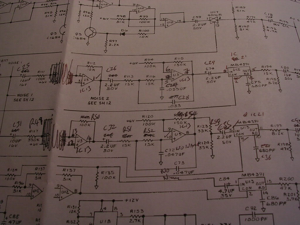
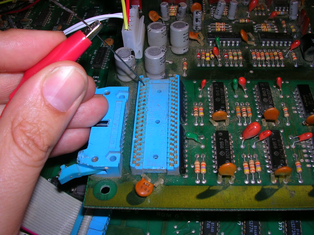
Time for the schematic, even tho it was for a different board layout and the component IDs and locations made no sense it was likely that the actual circuit was the same, what was useful was that it showed how the sounds are actually triggered. The ribbon cable feeds an 8 bit bus, 2 data lines, and a couple of control lines to an 8255 chip which is a parallel peripheral interface chip. All this chip is doing is pulling low lines on the audio board that trigger the sound generator sections of the circuit, and as these were labelled with the sound effect name I was able to trigger them individually myself by running the board with the 8255 unplugged and connecting the relevant output pins on the empty 8255 socket to ground, which is what the 8255 would do anyway under the direction of the main board. Pretty handy as in the game so many sounds occur at once it is hard to spot which one is having issues.
So, armed with a de-soldering iron cleaning poker clipped that was connected to system ground I could do this...
Only the ship explosion and the missile explosion are wrong, so time for more schematic diving. This time I had to print out the four A4 pages of the manual that had the audio schamtics as I had to work in from the s-exp and the m-exp trigger lines and follow the circuit path through to the output line that connects to the amplifier.
It was more likely that it was a single fault that was causing both issues so I needed to know where the common circuitry for these two sounds was. It seems that there were a couple of 555 timer based white noise generators on the board that were constantly running, producing signals called "Noise 1" and "Noise 2", and the schematic suggests that these were the component parts of the explosion sound effects. As one of the explosion sounds on this board was still healthy, and also because I could see the related 555 timers buzzing away I was fairly sure that section was still fine. So the fault was more likely to be downstream of the "noise 1 and 2" sections of the board, somewhere in the tangle of Op-Amps. On the schematics these two sound effects take different paths through different chips, but after half an hour of tracing and updating the chip locations on the diagram to match this board it became clear that on this layout the paths are common at this point...
... through 4 op-amps and a two MB4391s. The MB4391s are actually Sega chips on this board and although MB4391 does seem to excite the datasheet mining websites none of them had any info on what these actually are. The four op-amps (the triangle symbols) on the diagram above all resided on a single quad op-amp chip, an LM324 at IC13 on this board.
At this point the fault was coming and going, sometimes it was a faint hiss, other times it was only slightly distorted, but I found I could sometimes annoy the fault by touching the pins of this op-amp. When it was very faint and hissy I had no effect, when it was almost correct I could cause it to fail about 50% of the time. I could also confirm that touching the Sega upstream chip and the associated passive components had no effect at all. So I went mining in my scrap box and found and LM324 on an old bootleg board. When the original one was replaced I was hopeful this would be the final cure - it wasn't. The ship explosion was totally missing and the missile explosion was even more distorted, clearly this was a bad LM324 too.
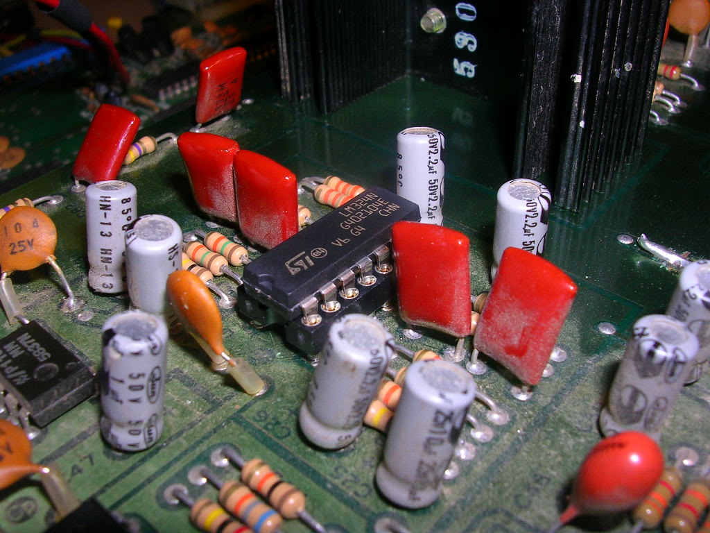
So another lunchtime walk to to jaycar, and I was $2 lighter and this beauty ended up on the board.
I resorted to a socket here because I didn't want to risk having to take this off the board again to troubleshoot further as there are only so many times a PCB will survive the heat cycle, plus with a socket you can bend pins out of the way to disconnect parts of a chip which can be pretty useful.
Thankfully it wasn't an issue because this new LM324 completely fixed the two explosion effects.
All that remains now is to refit the board supports, install new ones to replace the knackered ones and shrink the heatsink on the harness!
Job done!
