PCB Repair Logs Berzerk: Difference between revisions
mNo edit summary |
mNo edit summary |
||
| (5 intermediate revisions by the same user not shown) | |||
| Line 5: | Line 5: | ||
<tr class="> | <tr class="> | ||
<td colspan="2" class="" style="text-align:center;">[[Image:marquee_berzerk.jpg|200px]]</td> | <td colspan="2" class="" style="text-align:center;">[[Image:marquee_berzerk.jpg|200px]]</td> | ||
</tr> | |||
<tr class=""> | |||
<th scope="row" style="text-align:left; white-space: nowrap;">Manufacturer</th> | |||
<td class="" style="">[[PCB_Manufacturers_Stern|Stern]]</td> | |||
</tr> | |||
<tr class=""> | |||
<th scope="row" style="text-align:left; white-space: nowrap;">Year</th> | |||
<td class="" style="">1980</td> | |||
</tr> | </tr> | ||
<tr class=""> | <tr class=""> | ||
| Line 12: | Line 20: | ||
<tr class=""> | <tr class=""> | ||
<th scope="row" style="text-align:left; white-space: nowrap;">Pin Out</th> | <th scope="row" style="text-align:left; white-space: nowrap;">Pin Out</th> | ||
<td class="" style=""> | <td class="" style="">[[Pinouts_Berzerk_Pinout|Pinout]]</td> | ||
</tr> | </tr> | ||
</table></p> | </table></p> | ||
| Line 30: | Line 38: | ||
SB-1000: Sound FX | SB-1000: Sound FX | ||
VSU-1000: Voice Generator Board | VSU-1000: Voice Generator Board | ||
<br> | |||
<br> | |||
[[File:Pcb repair berzerk 1.jpg]] | |||
<br> | |||
<br> | |||
Was a real learning experience for me. I'll list the problems with each individual boards. I left the 2 sound boards off while working on it. | |||
ZPU-1000 | |||
I'll be making a JAMMA harness for this so this is the pins i used for this board. The pins are clearly marked from right to left 1-10<br> | |||
1 - Book keeping<br> | |||
2 - Ground<br> | |||
5 - +5<br> | |||
9 - +5<br> | |||
Rest are not used, there is pins there for -5 and +12 but are not needed unless you use some queerbo roms. | Rest are not used, there is pins there for -5 and +12 but are not needed unless you use some queerbo roms. | ||
What a mess, I've read battery acid damage on these pcbs are common and this one was no exception. I was very lucky that all tracks were intact. | What a mess, I've read battery acid damage on these pcbs are common and this one was no exception. I was very lucky that all tracks were intact. | ||
All the roms were missing on the pcb so replaced those, fired her up...nothing the test LED stays on. | All the roms were missing on the pcb so replaced those, fired her up...nothing the test LED stays on. | ||
<br> | |||
<br> | |||
[[File:Pcb repair berzerk 2.jpg]] | |||
<br> | |||
<br> | |||
First things you always check with a dead pcb is the clock(pin 6) and the reset(pin 26). Clock was pulsing fine but reset was stuck low. | First things you always check with a dead pcb is the clock(pin 6) and the reset(pin 26). Clock was pulsing fine but reset was stuck low. | ||
Did some reading on the net about this, when using a switch mode power supply you have to run a jumper across the diode @ CR26 | Did some reading on the net about this, when using a switch mode power supply you have to run a jumper across the diode @ CR26 | ||
| Line 61: | Line 79: | ||
No issues with this PCB, took out all the 2114 rams and tested them on other boards all worked fine. | No issues with this PCB, took out all the 2114 rams and tested them on other boards all worked fine. | ||
Let me start by | Let me start by saying **** when those old crappy 4027 rams go they get super hot and I got the blisters to prove it! The 4027 ram is pretty much the same as the common 4116 ram used on Defender and many other old pcb but has 1 less address line ad a CS(Chip Select) pin, they also use 3 voltages +12, +5 and -5. | ||
The 4027 ram is pretty much the same as the common 4116 ram used on Defender and many other old pcb but has 1 less address line ad a CS(Chip Select) pin, they also use 3 voltages +12, +5 and -5. | |||
I decided before I did any diagnostics to replace all the sockets for the rams and the 2 big logic chips(74ls181's). | I decided before I did any diagnostics to replace all the sockets for the rams and the 2 big logic chips(74ls181's). | ||
<br> | |||
<br> | |||
[[File:Pcb repair berzerk 3.jpg]] | |||
<br> | |||
<br> | |||
[[File:Pcb repair berzerk 4.jpg]] | |||
<br> | |||
<br> | |||
I've also decided to do away with the 4027 rams and use 4164 rams which only use +5 thus running much cooler, to do this i had to remove the following caps used on the +12 line c77, c88,c106, c66, c100 and c82. | I've also decided to do away with the 4027 rams and use 4164 rams which only use +5 thus running much cooler, to do this i had to remove the following caps used on the +12 line c77, c88,c106, c66, c100 and c82. | ||
I | I couldn't get the pcb to work so I ordered some of the rarer chips off the PCB from futurelec namely 74ls01,181,155,75 and some cmod chips that are used on the sound board 4051, 4053. | ||
With the new chips at hand I changed the 2 74ls181 which had broken legs, still nothing the rams outputs were dead. | With the new chips at hand I changed the 2 74ls181 which had broken legs, still nothing the rams outputs were dead. | ||
Doing some poking around with the logic probe i found a suspect counter 74ls161 @ 4G, piggy backing another chip on top gave me stuff on the screen | Doing some poking around with the logic probe i found a suspect counter 74ls161 @ 4G, piggy backing another chip on top gave me stuff on the screen | ||
Replaced the chip game fired right up now onto sound. | Replaced the chip game fired right up now onto sound. | ||
<br> | |||
<br> | |||
[[File:Pcb repair berzerk 5.jpg]] | |||
<br> | |||
<br> | |||
There are a few uncommon chips on this PCB some I managed to get from futurelec (4053, 4051 and MC6804) a couple I had to get from Rockby (cheers The Prof for the link) which are MC14175 and MC14562 both of which were not needed in the repair but handy to have to keep my Berzerk going for many years to come. For 10 of each of these it cost me $50 so not cheap either! | There are a few uncommon chips on this PCB some I managed to get from futurelec (4053, 4051 and MC6804) a couple I had to get from Rockby (cheers The Prof for the link) which are MC14175 and MC14562 both of which were not needed in the repair but handy to have to keep my Berzerk going for many years to come. For 10 of each of these it cost me $50 so not cheap either! | ||
Problem: missing 2 sounds, the shock sound when you run into a wall and the sound when you shoot a robot. the fire sound was | '''Problem:''' missing 2 sounds, the shock sound when you run into a wall and the sound when you shoot a robot. the fire sound was okay.<br> | ||
Fixed: 3 chips at fault all in the noise generator section of the pcb. 4053 Cmos @ B6, 74ls74 @ B8 and 74ls86 @ A8. All sounds now perfect. | '''Fixed:''' 3 chips at fault all in the noise generator section of the pcb. 4053 Cmos @ B6, 74ls74 @ B8 and 74ls86 @ A8. All sounds now perfect.<Br> | ||
This pcb i worried about the most because it has the voice generator chip TSI S14001A, only thing missing was a 2716 rom @ 2C. Programmed the rom up works fine! woohoo! | This pcb i worried about the most because it has the voice generator chip TSI S14001A, only thing missing was a 2716 rom @ 2C. Programmed the rom up works fine! woohoo! | ||
Latest revision as of 08:25, 5 February 2013
Berzerk
 |
|
| Manufacturer | Stern |
|---|---|
| Year | 1980 |
| PCB Image | Reserved |
| Pin Out | Pinout |
Repairer: Arcade King
Forum Thread: Berzerk PCB Repair
I bought a dedicated LAI Berzerk cab off John, defiantly a lot of work but It will be worth it.
Berzerk is a prick of a board set to work on easily the largest I've seen thus far. Not including the PSU and filter board (which I won't be using) there are 5 pcbs that make up Berzerk
ZPU-1000: Main CPU board.
BSC-1000: Colour overlay pcb.
VFB-1000: Video Board
SB-1000: Sound FX
VSU-1000: Voice Generator Board
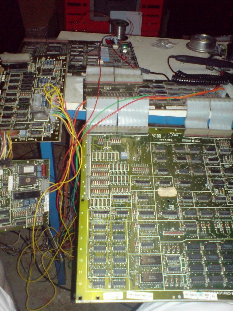
Was a real learning experience for me. I'll list the problems with each individual boards. I left the 2 sound boards off while working on it.
ZPU-1000
I'll be making a JAMMA harness for this so this is the pins i used for this board. The pins are clearly marked from right to left 1-10
1 - Book keeping
2 - Ground
5 - +5
9 - +5
Rest are not used, there is pins there for -5 and +12 but are not needed unless you use some queerbo roms.
What a mess, I've read battery acid damage on these pcbs are common and this one was no exception. I was very lucky that all tracks were intact.
All the roms were missing on the pcb so replaced those, fired her up...nothing the test LED stays on.
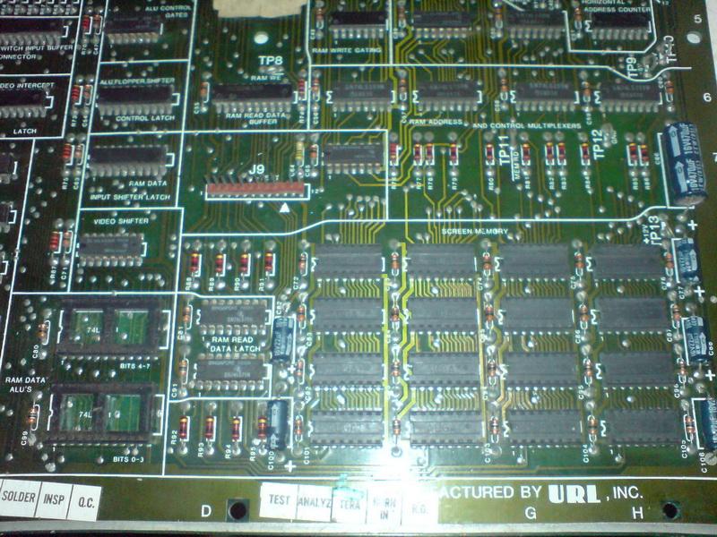
First things you always check with a dead pcb is the clock(pin 6) and the reset(pin 26). Clock was pulsing fine but reset was stuck low.
Did some reading on the net about this, when using a switch mode power supply you have to run a jumper across the diode @ CR26
OK now the LED flashes once which means by going from the manual a rom issue.
Going through all the roms I found the rom @ C1 pin 23 was dead, this rom is the test rom and that pin leads back to the CPU test Jumper. The jumper had cold solder joints and the track to the socket was pretty bad. I decided to replace the socket fixed the trace.
Right game is going through its test cycle, i get 3 LED flashes which means rom/rams ok the next test is suppose to be the VFB-1000 but it stops after 3. At this point I noticed a lot corrosion on the interconnect pins on the cpu and video boards so I replaced them, no change though still stop at 3 flashes and nothing on the screen at all.
After game working Issues.
Problem: Game boots up with 5 high scores all with random garbage and 37 credits. Fix: Don't know if it should do this to begin with but I solved it by adding in a 3.6v nicad battery going into the book keeping and resetting all the values.
No issues with this PCB, took out all the 2114 rams and tested them on other boards all worked fine.
Let me start by saying **** when those old crappy 4027 rams go they get super hot and I got the blisters to prove it! The 4027 ram is pretty much the same as the common 4116 ram used on Defender and many other old pcb but has 1 less address line ad a CS(Chip Select) pin, they also use 3 voltages +12, +5 and -5.
I decided before I did any diagnostics to replace all the sockets for the rams and the 2 big logic chips(74ls181's).
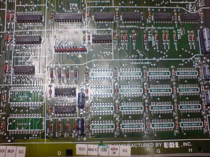
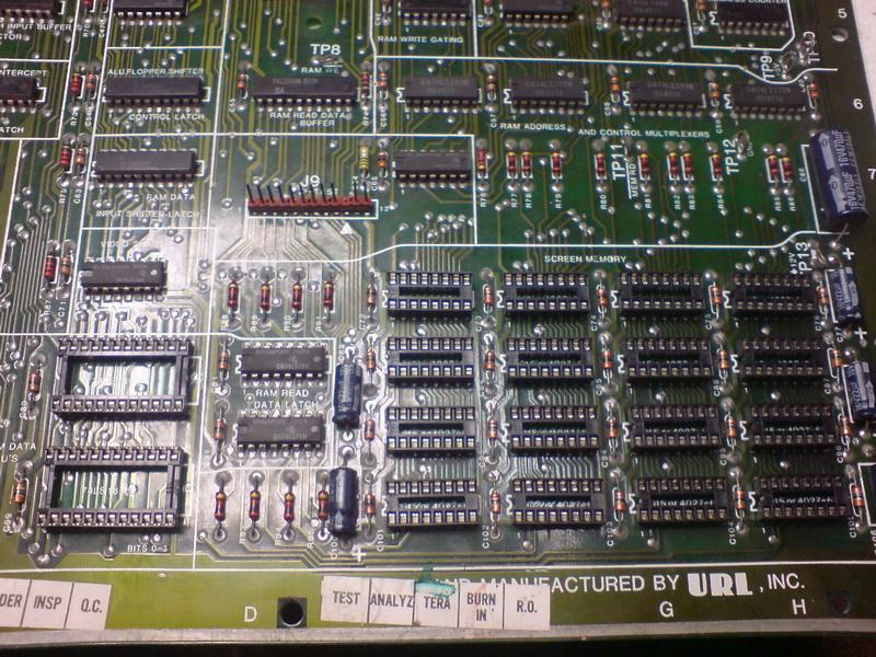
I've also decided to do away with the 4027 rams and use 4164 rams which only use +5 thus running much cooler, to do this i had to remove the following caps used on the +12 line c77, c88,c106, c66, c100 and c82.
I couldn't get the pcb to work so I ordered some of the rarer chips off the PCB from futurelec namely 74ls01,181,155,75 and some cmod chips that are used on the sound board 4051, 4053. With the new chips at hand I changed the 2 74ls181 which had broken legs, still nothing the rams outputs were dead.
Doing some poking around with the logic probe i found a suspect counter 74ls161 @ 4G, piggy backing another chip on top gave me stuff on the screen
Replaced the chip game fired right up now onto sound.
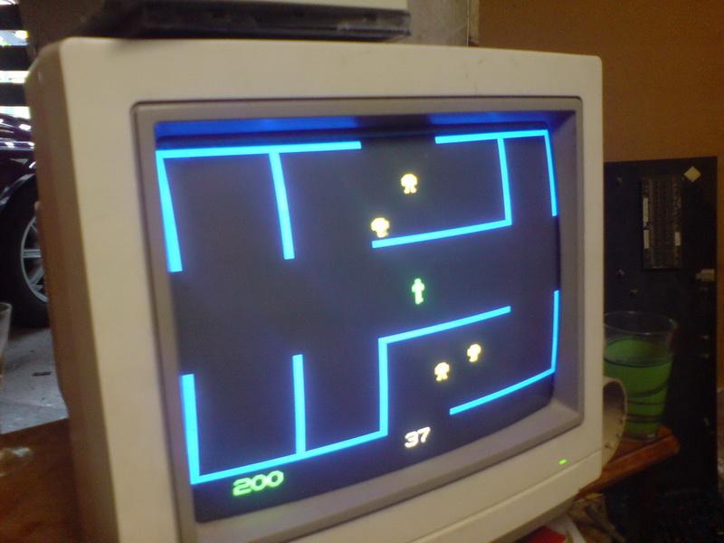
There are a few uncommon chips on this PCB some I managed to get from futurelec (4053, 4051 and MC6804) a couple I had to get from Rockby (cheers The Prof for the link) which are MC14175 and MC14562 both of which were not needed in the repair but handy to have to keep my Berzerk going for many years to come. For 10 of each of these it cost me $50 so not cheap either!
Problem: missing 2 sounds, the shock sound when you run into a wall and the sound when you shoot a robot. the fire sound was okay.
Fixed: 3 chips at fault all in the noise generator section of the pcb. 4053 Cmos @ B6, 74ls74 @ B8 and 74ls86 @ A8. All sounds now perfect.
This pcb i worried about the most because it has the voice generator chip TSI S14001A, only thing missing was a 2716 rom @ 2C. Programmed the rom up works fine! woohoo! If anybody knows where I can buy a spare S14001A please let me know!