PCB Repair Logs Frog: Difference between revisions
Created page with "==Frog== <p><table class="infobox vevent" style="width:22em;" cellspacing="5"> <caption class="summary" style=""><b>Frog</b></caption> <tr class="> <td colspan="2" class="" s..." |
mNo edit summary |
||
| (13 intermediate revisions by the same user not shown) | |||
| Line 5: | Line 5: | ||
<tr class="> | <tr class="> | ||
<td colspan="2" class="" style="text-align:center;">[[Image:Frog-marquee.png|200px]]</td> | <td colspan="2" class="" style="text-align:center;">[[Image:Frog-marquee.png|200px]]</td> | ||
</tr> | |||
<tr class=""> | |||
<th scope="row" style="text-align:left; white-space: nowrap;">Manufacturer</th> | |||
<td class="" style="">Unknown</td> | |||
</tr> | |||
<tr class=""> | |||
<th scope="row" style="text-align:left; white-space: nowrap;">Year</th> | |||
<td class="" style="">1981</td> | |||
</tr> | </tr> | ||
<tr class=""> | <tr class=""> | ||
<th scope="row" style="text-align:left; white-space: nowrap;">PCB Image</th> | <th scope="row" style="text-align:left; white-space: nowrap;">PCB Image</th> | ||
<td class="" style=""> | <td class="" style="">[http://wiki.aussiearcade.com.au/index.php/File:Frog_pcb.jpg Frog]</td> | ||
</tr> | </tr> | ||
<tr class=""> | <tr class=""> | ||
<th scope="row" style="text-align:left; white-space: nowrap;">Pin Out</th> | <th scope="row" style="text-align:left; white-space: nowrap;">Pin Out</th> | ||
<td class="" style=""> | <td class="" style="">[[PCB_Pinouts_Konami_Classic|Frog Pinout]]</td> | ||
</tr> | </tr> | ||
</table></p> | </table></p> | ||
__TOC__ | |||
=== Board 1 === | |||
<br> | |||
'''Repairer:''' [http://www.aussiearcade.com.au/member.php/1-Arcade-King Arcade King]<br> | '''Repairer:''' [http://www.aussiearcade.com.au/member.php/1-Arcade-King Arcade King]<br> | ||
'''Forum Thread:''' [http://www.aussiearcade.com.au/showthread.php/293-Frogger Frog PCB Repair]<br> | '''Forum Thread:''' [http://www.aussiearcade.com.au/showthread.php/293-Frogger Frog PCB Repair]<br> | ||
Won this one a few weeks back. | Won this one a few weeks back. | ||
Very happy with this board, be nice if I could make it say Frogger on the title screen | '''Problem:''' Garbage on the screen, frogs visible and game seems to be playing<br> | ||
'''Fix:''' Bad 2114 ram at IC86 | |||
<br> | |||
<p>[[File:Frog garbled graphics.jpg]]</p> | |||
<br> | |||
'''Problem:''' Board decided to die<br> | |||
'''Fix:''' 74LS368 at IC73 | |||
'''Problem:''' Colour of Frog wrong. Frog would have white in the center instead of yellow and showed up red at the bottom of the screen when demo on, some text was also wrong colour.<br> | |||
'''Fix:''' There is a hack to correct colours on this board. Pin 15 of the 74LS377(IC61) was connected to pin 4 of a 74LS20(IC36). Moving the wire to pin 5 of the 74LS20 fixed the colours on the frog. | |||
'''Problem:''' No sound<br> | |||
'''Fixed:''' z80 on sound board | |||
'''Problem:''' Background colours were wrong, top colour was a a royal blue while the bottom was a navy blue which is what the top was suppose to be.<br> | |||
<br> | |||
<p>[[File:frog bad background colour.jpg]]</p> | |||
<br> | |||
'''Fix:''' From playing around with the Scamble to Frogger hack I learned the background colours went through a 74ls08. Shorting inputs at 4 and 5 would make the entire screen navy blue while leaving the output ping 6 out would fix it entirly. Shorting the two inputs were not a option for me so i traced everything back to a 74126. To cut a long story short there are 2 470 ohm resistors 1 above and below this 74126 chip both dictating the final colour of the background. Removing the resistor at the top fixed the colours. Both resistors look like they have been replaced. | |||
<br> | |||
<p>[[File:frog fixed.jpg]]</p> | |||
<br> | |||
If [http://www.arcade-museum.com/ Klov] is anything to go by FROG was a bootleg Frogger with modified colours. This board would appear to look the same as the Konami/Sega one but wont run the programs. | |||
There was some wiring done (poorly) to a 74ls377 I now know was done to correct the colours back to how Frogger looks. | |||
Very happy with this board, be nice if I could make it say Frogger on the title screen. Any programmers in our little group feel like some hacking? | |||
<br> | |||
<br> | |||
=== Board 2 === | |||
<br> | |||
'''Repairer:''' [http://www.aussiearcade.com.au/member.php/695-dav000616 dav000616]<br> | |||
'''Forum Thread:''' [http://www.aussiearcade.com.au/showthread.php/12741-Konami-Frogger-Bootleg Frogger (Bootleg) PCB Repair]<br> | |||
Brought this off ebay 12mths ago and almost got burnt on the deal but that's another story. Hooked it up and got nothing but a blank screen. | |||
The board layout was identical to the sega frogger schematics so I used this for reference. I hooked up my sega board and made note of the control pins on the cpu. For memory there were 3 pins, BUSAK, BUSREQ and WAIT that were different. | |||
WAIT was held high instead of high low pulsing so I started here. Traced Wait back to a 74ls161 at IC82 which has pulsing inputs but no outputs. Piggybacked a 74LS161 and turned it on, still didn't have a picture but the outputs were pulsing now and I saw a small horizontal flicker of video so I cut the 161 out and soldered in another and it now lives. | |||
<br> | |||
=== Board 3 === | |||
<br> | |||
'''Repairer:''' [http://www.aussiearcade.com.au/member.php/1983-Womble Womble]<br> | |||
'''Forum Thread:''' [http://www.aussiearcade.com.au/showthread.php/56223-Frog-%28Frogger-Bootleg%29-Repair-Log Frog PCB Repair]<br> | |||
Felixthedog dropped by to pick up some stuff and came bearing this... | |||
<br> | |||
<p>[[File:Frog Repair 3 01.jpg]]</p> | |||
<br> | |||
...a bootleg PCB of unknown status that was helpfully labelled "FROG", the bootleg version of Frogger, from the era when bootleggers did at least change the game of the games they ripped off (Galaxians became Gallax, Galaga becomes Gallag, Amidar becomes Amigo and Frogger becomes Frog). | |||
<br> | |||
<p>[[File:Frog Repair 3 02.jpg]]</p> | |||
<br> | |||
There were a couple of bodgy repairs on the main board, some loose poly caps which got fitted properly and a missing 6.8uF tantalum cap related to the 741 op-amp. This seems to be a decoupling cap for the negative bias rail on the 741, the board seems perfectly happy without so the fact I have nothing suitable to replace it with doesn't bother me. | |||
The harness was pretty messy and was soldered to the edge connector, which would be a hanging offence if I was king. FTD had been told there was a problem to do with the 5V, one of the wires had come loose. So after fixing that I fired it up and it works, very nearly perfectly. | |||
<br> | |||
<p>[[File:Frog Repair 3 03.jpg]]</p> | |||
<br> | |||
<p>[[File:Frog Repair 3 04.jpg]]</p> | |||
<br> | |||
My repair bench has no speaker or inputs attached these days so it got transferred to my main cabinet for a play test. It was playable and we had music, but no user noises, no coin up, no hopping and no win/die sound effects. | |||
The first port of call was the AY-3-8910 sound chip seen in the top right here... | |||
<br> | |||
<p>[[File:Frog Repair 3 05.jpg]]</p> | |||
<br> | |||
... this is a three channel audio tone generator chip (amongst other things) and a quick poke with the scope showed there was output on channels B and C, but A was doing nothing. This could be by design but it seemed unlikely, on close inspection the AY had taken a hit one one leg, it was bent down and had broken away from the package body leaving a gap. | |||
<br> | |||
<p>[[File:Frog Repair 3 06.jpg]]</p> | |||
<br> | |||
This may or may not have broken the environmental seal on the chip but its another clue. So I whipped it off the board, fitted a socket and dropped in another AY chip - no change with the missing sfx, however the board was now misbehaving in a new way - the background tune kept restarting, often whenever there was an input from the controls. | |||
The fact the PCB had a couple of M5L8255AP chips was suspicious have seen boards of this era using these on the control inputs and they do very odd things when they go bad. The proximity to the AY suggested the control inputs were more related to the user audio triggering than you would expect. I still have the old Amigo PCB that had the haunted input fault due to a bad 8255 so I had one known good chip to use as a spare. | |||
I desoldered the 8255 directly attached to the controls on the PCB and fitted a socket (I should point out that all the photos in this repair log were taken after the fix so there are sockets shown where originally were none, as the controls were actually working it would have made more sense to hit up the second one first but hindsight is 20/20. | |||
<br> | |||
<p>[[File:Frog Repair 3 07.jpg]]</p> | |||
<br> | |||
Anyway, with a good 8255 (the Intel one) at that location there was no change at all, so I moved on to the second one, fitted a socket and dropped in the 8255 I pulled from the first location, and this fixed the fault. | |||
The board still had one of my spare AY chips onBoard which was now singing away. Swapping in the original AY proved it too was faulty, some of the music was now playing slightly out of tune and the hop noises were just a buzz. It was retired to the bin and the spare was reinstalled. | |||
The harness is still bugging me, I might get round to fixing that, but I also might not.<br> | |||
[[PCB_Repair_Index|Back to PCB Repair Index]] | |||
Latest revision as of 12:37, 5 February 2013
Frog
 |
|
| Manufacturer | Unknown |
|---|---|
| Year | 1981 |
| PCB Image | Frog |
| Pin Out | Frog Pinout |
Board 1
Repairer: Arcade King
Forum Thread: Frog PCB Repair
Won this one a few weeks back.
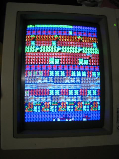
Problem: Garbage on the screen, frogs visible and game seems to be playing
Fix: Bad 2114 ram at IC86
Problem: Board decided to die
Fix: 74LS368 at IC73
Problem: Colour of Frog wrong. Frog would have white in the center instead of yellow and showed up red at the bottom of the screen when demo on, some text was also wrong colour.
Fix: There is a hack to correct colours on this board. Pin 15 of the 74LS377(IC61) was connected to pin 4 of a 74LS20(IC36). Moving the wire to pin 5 of the 74LS20 fixed the colours on the frog.
Problem: No sound
Fixed: z80 on sound board
Problem: Background colours were wrong, top colour was a a royal blue while the bottom was a navy blue which is what the top was suppose to be.
Fix: From playing around with the Scamble to Frogger hack I learned the background colours went through a 74ls08. Shorting inputs at 4 and 5 would make the entire screen navy blue while leaving the output ping 6 out would fix it entirly. Shorting the two inputs were not a option for me so i traced everything back to a 74126. To cut a long story short there are 2 470 ohm resistors 1 above and below this 74126 chip both dictating the final colour of the background. Removing the resistor at the top fixed the colours. Both resistors look like they have been replaced.
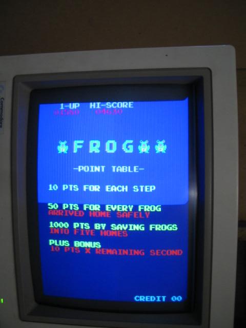
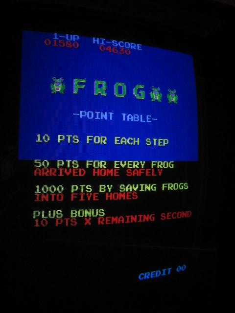
If Klov is anything to go by FROG was a bootleg Frogger with modified colours. This board would appear to look the same as the Konami/Sega one but wont run the programs.
There was some wiring done (poorly) to a 74ls377 I now know was done to correct the colours back to how Frogger looks.
Very happy with this board, be nice if I could make it say Frogger on the title screen. Any programmers in our little group feel like some hacking?
Board 2
Repairer: dav000616
Forum Thread: Frogger (Bootleg) PCB Repair
Brought this off ebay 12mths ago and almost got burnt on the deal but that's another story. Hooked it up and got nothing but a blank screen.
The board layout was identical to the sega frogger schematics so I used this for reference. I hooked up my sega board and made note of the control pins on the cpu. For memory there were 3 pins, BUSAK, BUSREQ and WAIT that were different.
WAIT was held high instead of high low pulsing so I started here. Traced Wait back to a 74ls161 at IC82 which has pulsing inputs but no outputs. Piggybacked a 74LS161 and turned it on, still didn't have a picture but the outputs were pulsing now and I saw a small horizontal flicker of video so I cut the 161 out and soldered in another and it now lives.
Board 3
Repairer: Womble
Forum Thread: Frog PCB Repair
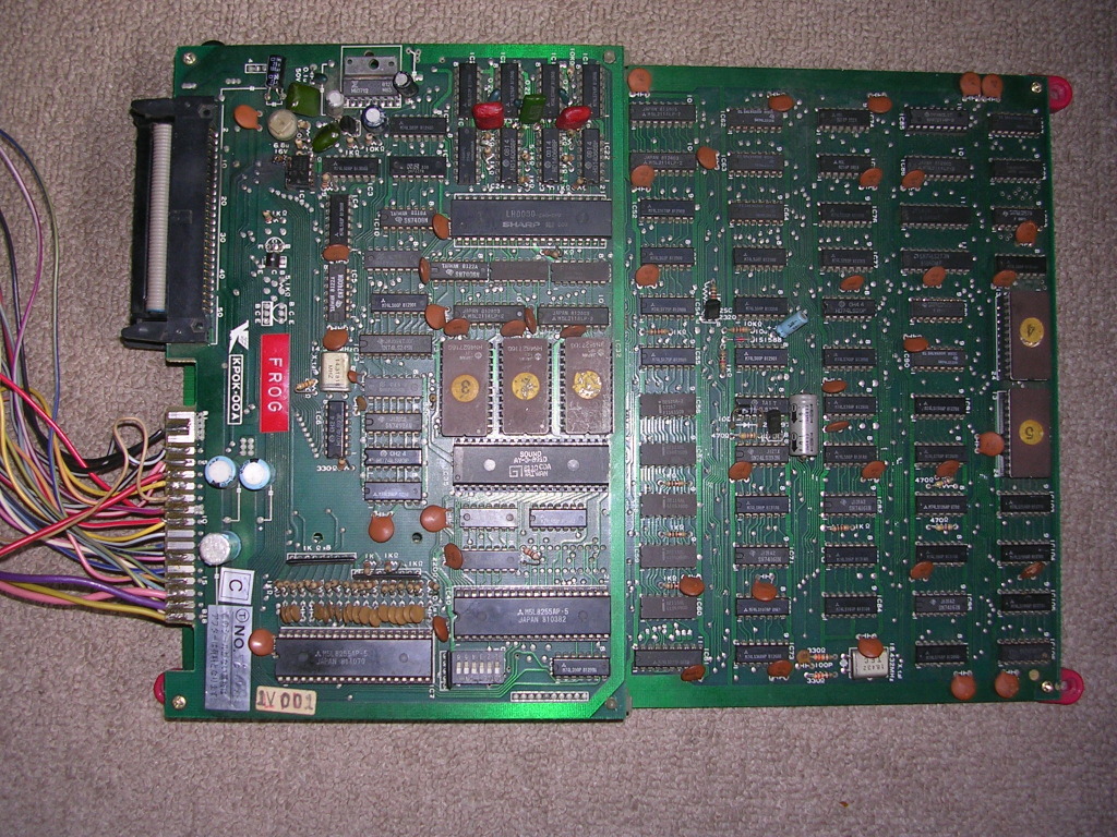
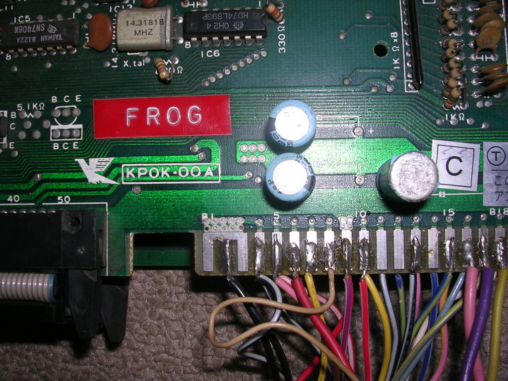
Felixthedog dropped by to pick up some stuff and came bearing this...
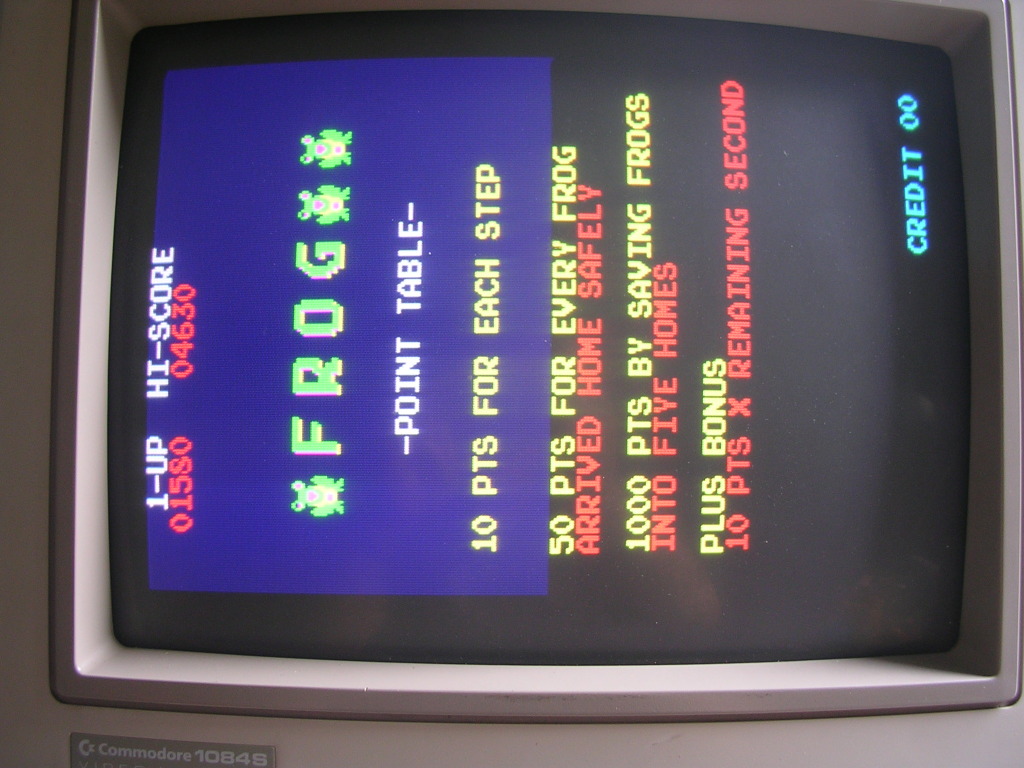
...a bootleg PCB of unknown status that was helpfully labelled "FROG", the bootleg version of Frogger, from the era when bootleggers did at least change the game of the games they ripped off (Galaxians became Gallax, Galaga becomes Gallag, Amidar becomes Amigo and Frogger becomes Frog).
There were a couple of bodgy repairs on the main board, some loose poly caps which got fitted properly and a missing 6.8uF tantalum cap related to the 741 op-amp. This seems to be a decoupling cap for the negative bias rail on the 741, the board seems perfectly happy without so the fact I have nothing suitable to replace it with doesn't bother me.
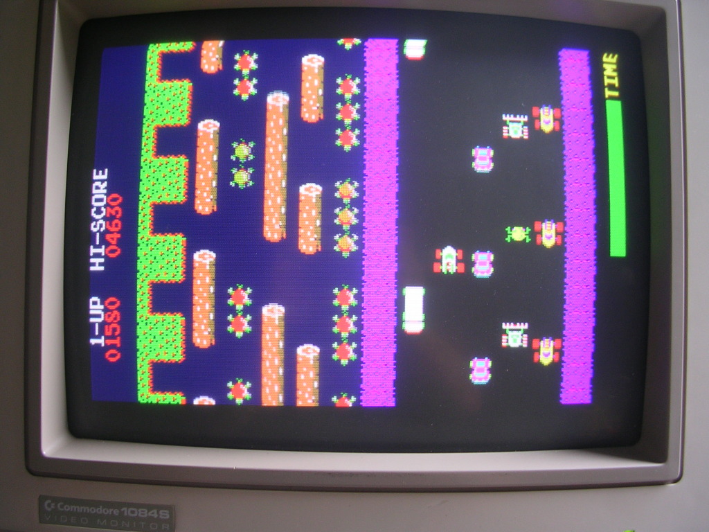
The harness was pretty messy and was soldered to the edge connector, which would be a hanging offence if I was king. FTD had been told there was a problem to do with the 5V, one of the wires had come loose. So after fixing that I fired it up and it works, very nearly perfectly.
My repair bench has no speaker or inputs attached these days so it got transferred to my main cabinet for a play test. It was playable and we had music, but no user noises, no coin up, no hopping and no win/die sound effects.
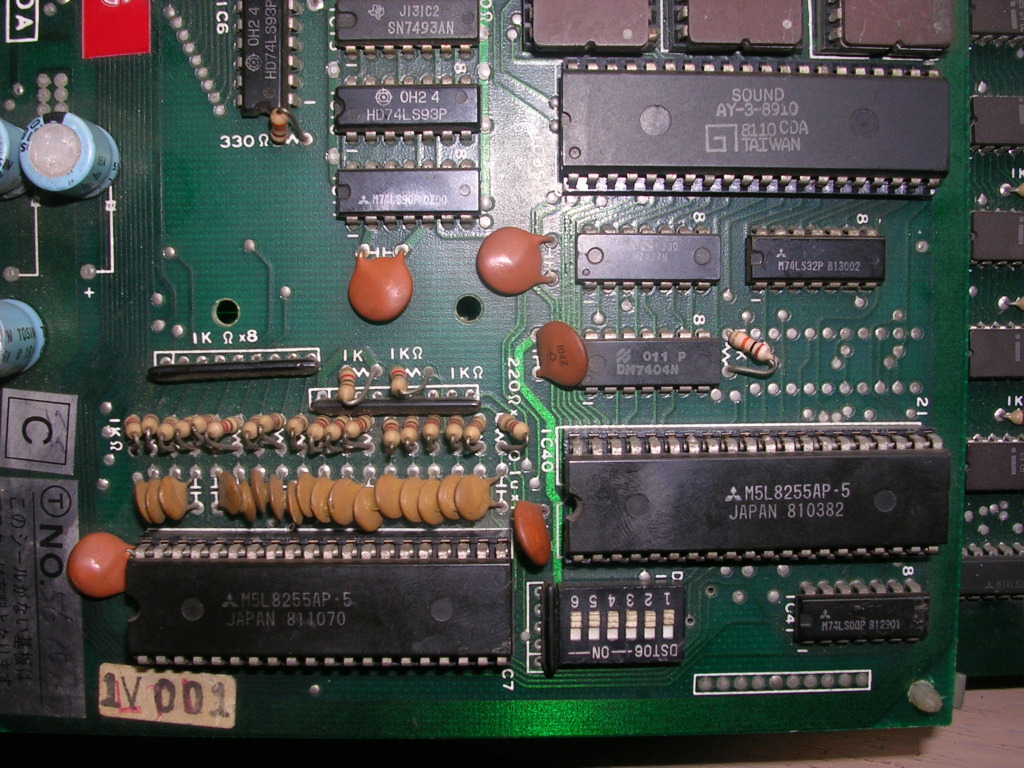
The first port of call was the AY-3-8910 sound chip seen in the top right here...
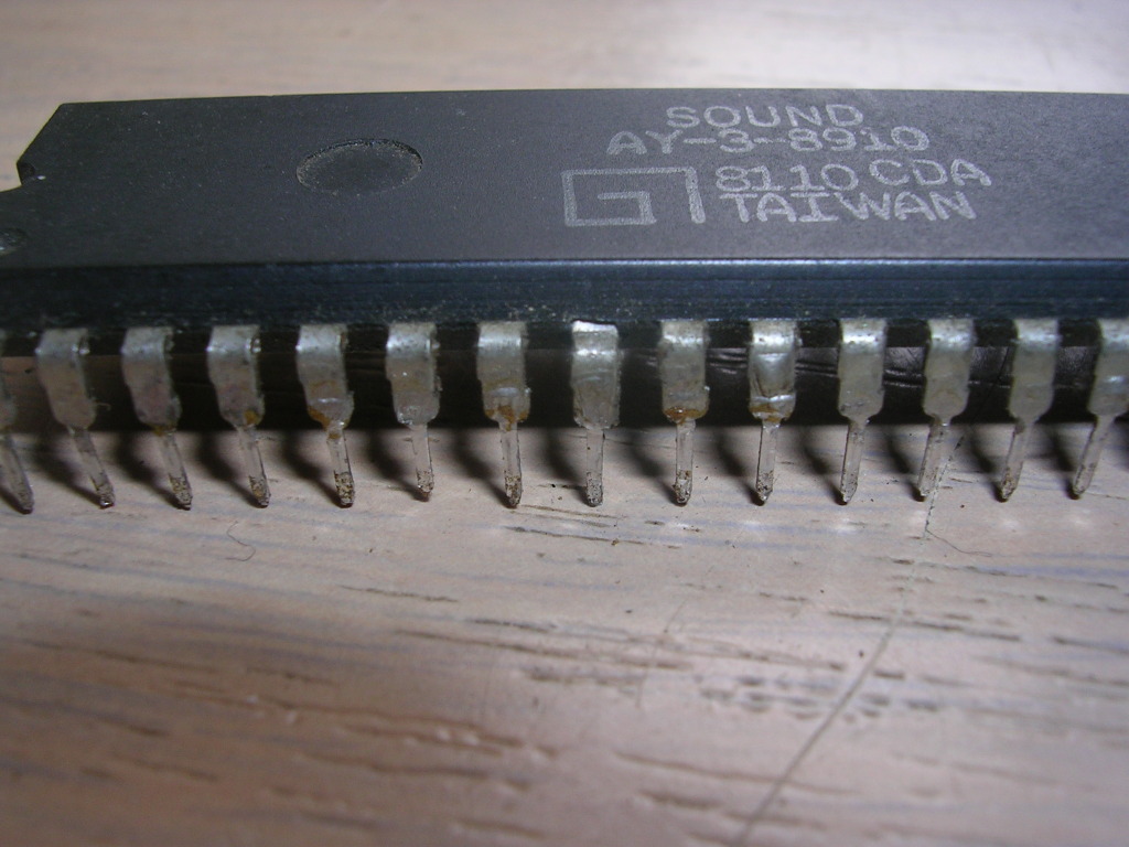
... this is a three channel audio tone generator chip (amongst other things) and a quick poke with the scope showed there was output on channels B and C, but A was doing nothing. This could be by design but it seemed unlikely, on close inspection the AY had taken a hit one one leg, it was bent down and had broken away from the package body leaving a gap.
This may or may not have broken the environmental seal on the chip but its another clue. So I whipped it off the board, fitted a socket and dropped in another AY chip - no change with the missing sfx, however the board was now misbehaving in a new way - the background tune kept restarting, often whenever there was an input from the controls.
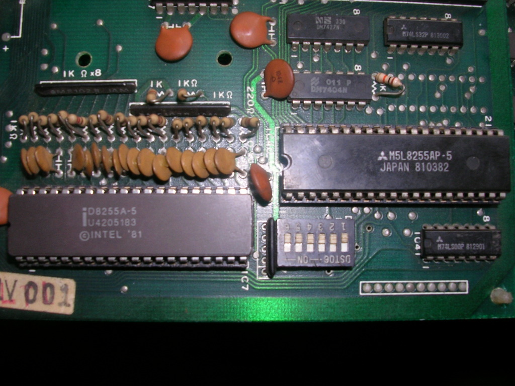
The fact the PCB had a couple of M5L8255AP chips was suspicious have seen boards of this era using these on the control inputs and they do very odd things when they go bad. The proximity to the AY suggested the control inputs were more related to the user audio triggering than you would expect. I still have the old Amigo PCB that had the haunted input fault due to a bad 8255 so I had one known good chip to use as a spare.
I desoldered the 8255 directly attached to the controls on the PCB and fitted a socket (I should point out that all the photos in this repair log were taken after the fix so there are sockets shown where originally were none, as the controls were actually working it would have made more sense to hit up the second one first but hindsight is 20/20.
Anyway, with a good 8255 (the Intel one) at that location there was no change at all, so I moved on to the second one, fitted a socket and dropped in the 8255 I pulled from the first location, and this fixed the fault.
The board still had one of my spare AY chips onBoard which was now singing away. Swapping in the original AY proved it too was faulty, some of the music was now playing slightly out of tune and the hop noises were just a buzz. It was retired to the bin and the spare was reinstalled.
The harness is still bugging me, I might get round to fixing that, but I also might not.
