PCB Repair Logs Midnight Resistance: Difference between revisions
mNo edit summary |
mNo edit summary |
||
| (8 intermediate revisions by the same user not shown) | |||
| Line 5: | Line 5: | ||
<tr class="> | <tr class="> | ||
<td colspan="2" class="" style="text-align:center;">[[Image:marquee_midnight_resistance.jpg|200px]]</td> | <td colspan="2" class="" style="text-align:center;">[[Image:marquee_midnight_resistance.jpg|200px]]</td> | ||
</tr> | |||
<tr class=""> | |||
<th scope="row" style="text-align:left; white-space: nowrap;">Manufacturer</th> | |||
<td class="" style="">[[PCB_Manufacturers_Nihon_Bussan/AV_Japan|Nihon Bussan/AV Japan]]</td> | |||
</tr> | |||
<tr class=""> | |||
<th scope="row" style="text-align:left; white-space: nowrap;">Year</th> | |||
<td class="" style="">1989</td> | |||
</tr> | </tr> | ||
<tr class=""> | <tr class=""> | ||
| Line 12: | Line 20: | ||
<tr class=""> | <tr class=""> | ||
<th scope="row" style="text-align:left; white-space: nowrap;">Pin Out</th> | <th scope="row" style="text-align:left; white-space: nowrap;">Pin Out</th> | ||
<td class="" style=""> | <td class="" style="">[[PCB_Pinouts_Jamma|Jamma]]</td> | ||
</tr> | </tr> | ||
</table></p> | </table></p> | ||
__TOC__ | |||
'''Repairer:''' [http://www.aussiearcade.com.au/member.php/1983-Womble Womble]<br> | '''Repairer:''' [http://www.aussiearcade.com.au/member.php/1983-Womble Womble]<br> | ||
'''Forum Thread:''' [http://www.aussiearcade.com.au/showthread.php/27221-Midnight-Resistance-Repair-Log Midnight Resistance PCB Repair]<br> | '''Forum Thread:''' [http://www.aussiearcade.com.au/showthread.php/27221-Midnight-Resistance-Repair-Log Midnight Resistance PCB Repair]<br> | ||
<br> | <br> | ||
=== Board 1 === | === Board 1 === | ||
Bought a Midnight Resistance board recently, was up with a buy-it-now very cheap so I grabbed it, I love the game, its the reason my cab has rotary sticks installed. | Bought a Midnight Resistance board recently, was up with a buy-it-now very cheap so I grabbed it, I love the game, its the reason my cab has rotary sticks installed. | ||
| Line 369: | Line 376: | ||
Hooked it up on my test bench and got nothing, blank dark screen and no sound. On the solder side there was some scuff marks and some dodgy looking tracks but everything buzzed through ok except for one obvious blown one which I jumpered with some hookup wire. It's the rightermost track of the 4here, looks kinda roasted. | Hooked it up on my test bench and got nothing, blank dark screen and no sound. On the solder side there was some scuff marks and some dodgy looking tracks but everything buzzed through ok except for one obvious blown one which I jumpered with some hookup wire. It's the rightermost track of the 4here, looks kinda roasted. | ||
<br> | |||
<br> | |||
[[File:Pcb repair midnight resistance 5 1.jpg]] | |||
<br> | |||
<br> | |||
However the damage was a long way from the CPU, RAM and program ROMs so it was unlikely to be the cause of a dead board. | However the damage was a long way from the CPU, RAM and program ROMs so it was unlikely to be the cause of a dead board. | ||
| Line 377: | Line 386: | ||
When powered up again, the scope showed activity on the two buses, but I still had a totally blank screen and no sound. Poking the scope at the JAMMA edge connectors showed I had sync but nothing on the RGB lines. Having fixed half a dozen MidRes boards I know my way around them quite well and the RGB channel output comes from a pair of 74ls174 chips at L21 and L22, usually Fujitsu brand and usually totally hosed. They did not disappoint, both chips were missing all their outputs and replacing these lit the board back up. I also replaced the final Fujitsu chip on the board, a 74ls367 that also tested as dead when removed. | When powered up again, the scope showed activity on the two buses, but I still had a totally blank screen and no sound. Poking the scope at the JAMMA edge connectors showed I had sync but nothing on the RGB lines. Having fixed half a dozen MidRes boards I know my way around them quite well and the RGB channel output comes from a pair of 74ls174 chips at L21 and L22, usually Fujitsu brand and usually totally hosed. They did not disappoint, both chips were missing all their outputs and replacing these lit the board back up. I also replaced the final Fujitsu chip on the board, a 74ls367 that also tested as dead when removed. | ||
<br> | |||
<br> | |||
[[File:Pcb repair midnight resistance 5 2.jpg]] | |||
<br> | |||
<br> | |||
[[File:Pcb repair midnight resistance 5 3.jpg]] | |||
<br> | |||
<br> | |||
[[File:Pcb repair midnight resistance 5 4.jpg]] | |||
<br> | |||
<br> | |||
I now had various screens from the attract mode showing up, as well as the backgrounds which scrolled around as they should. At this stage I also removed the sound section SRAM, another TMM2063 and another dead chip. Fitting a socket and installing another CXK5864 did nothing to restore the sound though. There were two remaining TMM2063 chips at A10 and A11 which deal with the foreground text and icons, again both these chips were dead so replacements were installed in sockets, which didn't actually change anything at this point in the proceedings. | I now had various screens from the attract mode showing up, as well as the backgrounds which scrolled around as they should. At this stage I also removed the sound section SRAM, another TMM2063 and another dead chip. Fitting a socket and installing another CXK5864 did nothing to restore the sound though. There were two remaining TMM2063 chips at A10 and A11 which deal with the foreground text and icons, again both these chips were dead so replacements were installed in sockets, which didn't actually change anything at this point in the proceedings. | ||
| Line 391: | Line 407: | ||
When hooked up again I could see that the address and databuses were running still, but the screen was once again blank. Several TMM2018 SRAM chips were now getting stinking hot too, one of a pair (B14) by the background mask ROMs and both of the screen pallet TMM2018s at J21 and J22. These were getting so hot that there was no chance they were going to pass any tests so I simply snipped the legs off each chip and desoldered the pins individually. As I was not convinced the board was worth losing any more decent sockets on I fitted a couple of tatty salvaged dual wipes and a couple of 6116 variant chips. This restored the display but the colours were even worse than before. | When hooked up again I could see that the address and databuses were running still, but the screen was once again blank. Several TMM2018 SRAM chips were now getting stinking hot too, one of a pair (B14) by the background mask ROMs and both of the screen pallet TMM2018s at J21 and J22. These were getting so hot that there was no chance they were going to pass any tests so I simply snipped the legs off each chip and desoldered the pins individually. As I was not convinced the board was worth losing any more decent sockets on I fitted a couple of tatty salvaged dual wipes and a couple of 6116 variant chips. This restored the display but the colours were even worse than before. | ||
<br> | |||
<br> | |||
[[File:Pcb repair midnight resistance 5 5.jpg]] | |||
<br> | |||
<br> | |||
[[File:Pcb repair midnight resistance 5 6.jpg]] | |||
<br> | |||
<br> | |||
I ignored partner chip of the overheating one as I didn't have any more non-decent sockets to risk, so moved on to the other missing screen elements, the foreground text/icons, and the sprite field. The data for these layers are mixed into the gfx data stream by two 7425s, the foreground text and icons by the one at H22 and the sprite layer by the one at H21. Both of these were dead, healthy inputs but no output. Replacing them both restored their respective layers, however the colour issues seemed to be getting worse, the background colour choice was fairly random, sometimes green, sometimes grey. | I ignored partner chip of the overheating one as I didn't have any more non-decent sockets to risk, so moved on to the other missing screen elements, the foreground text/icons, and the sprite field. The data for these layers are mixed into the gfx data stream by two 7425s, the foreground text and icons by the one at H22 and the sprite layer by the one at H21. Both of these were dead, healthy inputs but no output. Replacing them both restored their respective layers, however the colour issues seemed to be getting worse, the background colour choice was fairly random, sometimes green, sometimes grey. | ||
<br> | |||
<br> | |||
[[File:Pcb repair midnight resistance 5 7.jpg]] | |||
<br> | |||
<br> | |||
[[File:Pcb repair midnight resistance 5 8.jpg]] | |||
<br> | |||
<br> | |||
The background data was also partially missing as the RAM in this section was half missing, half dead which made the colour issue even more severe. | The background data was also partially missing as the RAM in this section was half missing, half dead which made the colour issue even more severe. | ||
<br> | |||
<br> | |||
[[File:Pcb repair midnight resistance 5 9.jpg]] | |||
<br> | |||
<br> | |||
[[File:Pcb repair midnight resistance 5 10.jpg]] | |||
<br> | |||
<br> | |||
[[File:Pcb repair midnight resistance 5 11.jpg]] | |||
<br> | |||
<br> | |||
I felt like I was getting somewhere again so I removed the TMM2018 that hadn't turned itself into a heater and dropped in two sockets and two new 2018 chips at B13 and B14. The backgrounds started to look a little better but now the foreground was rather dark and gloomy. | I felt like I was getting somewhere again so I removed the TMM2018 that hadn't turned itself into a heater and dropped in two sockets and two new 2018 chips at B13 and B14. The backgrounds started to look a little better but now the foreground was rather dark and gloomy. | ||
<br> | |||
<br> | |||
[[File:Pcb repair midnight resistance 5 12.jpg]] | |||
<br> | |||
<br> | |||
[[File:Pcb repair midnight resistance 5 13.jpg]] | |||
<br> | |||
<br> | |||
[[File:Pcb repair midnight resistance 5 14.jpg]] | |||
<br> | |||
<br> | |||
So I started to poke around the palette SRAMs chips I had replaced and found the problem, address lines A0 to A4 were silent and held low, these traced back to a pair of LS157 chips that had clearly been destroyed when the SRAM fried. Replacing these... | So I started to poke around the palette SRAMs chips I had replaced and found the problem, address lines A0 to A4 were silent and held low, these traced back to a pair of LS157 chips that had clearly been destroyed when the SRAM fried. Replacing these... | ||
<br> | |||
<br> | |||
[[File:Pcb repair midnight resistance 5 15.jpg]] | |||
<br> | |||
<br> | |||
...finally fixed the colour fault once and for all. | |||
<br> | |||
<br> | |||
[[File:Pcb repair midnight resistance 5 16.jpg]] | |||
<br> | |||
<br> | |||
[[File:Pcb repair midnight resistance 5 17.jpg]] | |||
<br> | |||
<br> | |||
[[File:Pcb repair midnight resistance 5 18.jpg]] | |||
<br> | |||
<br> | |||
The sprites were still not well tho.. | The sprites were still not well tho.. | ||
<br> | |||
<br> | |||
[[File:Pcb repair midnight resistance 5 19.jpg]] | |||
<br> | |||
<br> | |||
.. and there was a chip in the sound section that was starting to get extremely hot. | .. and there was a chip in the sound section that was starting to get extremely hot. | ||
<br> | |||
<br> | |||
[[File:Pcb repair midnight resistance 5 20.jpg]] | |||
<br> | |||
<br> | |||
So hot in fact that it was starting to smell, and as I didn't want the shite roasted out of the board I decided to focus on the sound for a while. Identifying the chip was fairly easy, a quick look in the MAME driver showed that the sound section had two CPUs, the small OKI 6295 by the amp and an HuC6280 made by Hudson Soft - the same CPU as used in the NEC TurboGrafx 16! Finding the pinout for that was a struggle but I finally found a text file version that confirmed it should have 80 pins and a clock signal on pin 10, which fit the bill for the chip that was cooking. | So hot in fact that it was starting to smell, and as I didn't want the shite roasted out of the board I decided to focus on the sound for a while. Identifying the chip was fairly easy, a quick look in the MAME driver showed that the sound section had two CPUs, the small OKI 6295 by the amp and an HuC6280 made by Hudson Soft - the same CPU as used in the NEC TurboGrafx 16! Finding the pinout for that was a struggle but I finally found a text file version that confirmed it should have 80 pins and a clock signal on pin 10, which fit the bill for the chip that was cooking. | ||
| Line 438: | Line 496: | ||
The only complicating factor was this was a surface mount chip, time to crack open the ChipQuik and lose my SMD virginity!! QuikChip is basically a very low melting point metal alloy designed to allow the removal of SMDs without expensive hardware, I bought some ages ago but had never needed to use it until now. You apply flux to the chip legs and melt in a length of the alloy, the original solder dissolves and due to it's low melting point it take so long to cool enought to harden that you can get all the legs molten at once, the chip then can then be slid off, and it works... | The only complicating factor was this was a surface mount chip, time to crack open the ChipQuik and lose my SMD virginity!! QuikChip is basically a very low melting point metal alloy designed to allow the removal of SMDs without expensive hardware, I bought some ages ago but had never needed to use it until now. You apply flux to the chip legs and melt in a length of the alloy, the original solder dissolves and due to it's low melting point it take so long to cool enought to harden that you can get all the legs molten at once, the chip then can then be slid off, and it works... | ||
<br> | |||
<br> | |||
[[File:Pcb repair midnight resistance 5 21.jpg]] | |||
<br> | |||
<br> | |||
Leaving the board in mint condition. | Leaving the board in mint condition. | ||
<br> | |||
<br> | |||
[[File:Pcb repair midnight resistance 5 22.jpg]] | |||
<br> | |||
<br> | |||
The donor chip got the same treatment... | The donor chip got the same treatment... | ||
<br> | |||
<br> | |||
[[File:Pcb repair midnight resistance 5 23.jpg]] | |||
<br> | |||
<br> | |||
...and was just as easily removed. Cleaning up the chip for reuse was straight forward, the QuikChip stay molten for so long you can just tap the chip on the desk and it mostly just falls off. A quick run over with the desoldering iron removed the rest. | ...and was just as easily removed. Cleaning up the chip for reuse was straight forward, the QuikChip stay molten for so long you can just tap the chip on the desk and it mostly just falls off. A quick run over with the desoldering iron removed the rest. | ||
Soldering it in place took a while until I changed to a chisel iron tip and used enough flux, then the new joints almost fell into place. | Soldering it in place took a while until I changed to a chisel iron tip and used enough flux, then the new joints almost fell into place. | ||
<br> | |||
<br> | |||
[[File:Pcb repair midnight resistance 5 24.png]] | |||
<br> | |||
<br> | |||
After going round with the meter checking for bridges, and fixing the two I couldn't see by eye, it was time to power up again. | After going round with the meter checking for bridges, and fixing the two I couldn't see by eye, it was time to power up again. | ||
| Line 464: | Line 530: | ||
On this board the sprite data lives in 4 mask ROMs at A3, A4, A5 and A6, their outputs were all active and all their inputs looked good. The fault was either the ROMs themselves or due to upstream chippery being damaged. Everything looked ok upstream but the large 160 pin "MXC 06" custom chip was a bit of an unknown quantity. I decided to give the solder side of the PCB another going over by eye in this area first and the first thing obvious thing was the burnt track I had repaired at the outset. The track was the A15 line to the sprite ROM bank, and although it was now bridged with hookup wire it was clear that this area of the board had been shorted out somehow and that track had taken the full force of the power supply before it nominated itself as the fuse and vaporised in various places. This is the exact sort of treatment that ROMs really do not like, although whether it was a dying mask ROM that cause it or not I will never know. The track went to the last of the 4 mask ROMs, called "03' and then hopped to 02, 01 and 00. So I desoldered the directly connected on and put it in my eprom reader. I had to make a small adaptor so it could be read as a 27c100 chip. Mask ROMs are often shorter than their EPROM equivalent as the data is built into the ROM as it is made, there is no programming step so no need for a programming pin. Thankfully this board comes in a few variants, some with normal EPROMs and some with mask roms, which just sit in the same socket set back 4 pins. All I had to do was use an old socket and bend the 5V pin out of the way and connect it in what was empty space on the reader socket, but where the power pin of a 27c100 would be. | On this board the sprite data lives in 4 mask ROMs at A3, A4, A5 and A6, their outputs were all active and all their inputs looked good. The fault was either the ROMs themselves or due to upstream chippery being damaged. Everything looked ok upstream but the large 160 pin "MXC 06" custom chip was a bit of an unknown quantity. I decided to give the solder side of the PCB another going over by eye in this area first and the first thing obvious thing was the burnt track I had repaired at the outset. The track was the A15 line to the sprite ROM bank, and although it was now bridged with hookup wire it was clear that this area of the board had been shorted out somehow and that track had taken the full force of the power supply before it nominated itself as the fuse and vaporised in various places. This is the exact sort of treatment that ROMs really do not like, although whether it was a dying mask ROM that cause it or not I will never know. The track went to the last of the 4 mask ROMs, called "03' and then hopped to 02, 01 and 00. So I desoldered the directly connected on and put it in my eprom reader. I had to make a small adaptor so it could be read as a 27c100 chip. Mask ROMs are often shorter than their EPROM equivalent as the data is built into the ROM as it is made, there is no programming step so no need for a programming pin. Thankfully this board comes in a few variants, some with normal EPROMs and some with mask roms, which just sit in the same socket set back 4 pins. All I had to do was use an old socket and bend the 5V pin out of the way and connect it in what was empty space on the reader socket, but where the power pin of a 27c100 would be. | ||
<br> | |||
<br> | |||
[[File:Pcb repair midnight resistance 5 2.jpg]] | |||
<br> | |||
<br> | |||
The chip dumped perfectly and came back as being a Midnight Resistance ROM ff03 - slightly disappointing. Chip 02 was desoldered and again read fine, however the dump was not recognised at all, and subsequent dumps all had differing checksums, a duff ROM!! The remaining two ROMs, 01 and 00 had been completely destroyed though, my reader flagged most of the pins as "out of spec"... | The chip dumped perfectly and came back as being a Midnight Resistance ROM ff03 - slightly disappointing. Chip 02 was desoldered and again read fine, however the dump was not recognised at all, and subsequent dumps all had differing checksums, a duff ROM!! The remaining two ROMs, 01 and 00 had been completely destroyed though, my reader flagged most of the pins as "out of spec"... | ||
<br> | |||
<br> | |||
[[File:Pcb repair midnight resistance 5 26.png]] | |||
<br> | |||
<br> | |||
...and the chips just gave totally empty reads, all FF which is exactly what I was hoping to see. | ...and the chips just gave totally empty reads, all FF which is exactly what I was hoping to see. | ||
With all four off the board... | With all four off the board... | ||
<br> | |||
<br> | |||
[[File:Pcb repair midnight resistance 5 27.jpg]] | |||
<br> | |||
<br> | |||
... I powered it up, this shows what you get with completely blank sprite data, all the data lines are held high by the pull-up resistor networks as there is no ROM data to pull them down., so all bits in the sprite area are on and take preference over the background for all RGB channels giving bright white blocks. | ... I powered it up, this shows what you get with completely blank sprite data, all the data lines are held high by the pull-up resistor networks as there is no ROM data to pull them down., so all bits in the sprite area are on and take preference over the background for all RGB channels giving bright white blocks. | ||
<br> | |||
<br> | |||
[[File:Pcb repair midnight resistance 5 28.png]] | |||
<br> | |||
<br> | |||
So, as the board can take either the shorter 28 pin mask ROMs, or 27c100s (32) pins all I had to do was clear the solder from the previously unused 4 holes per chip, fit some sockets and drop in three 27c100s containing the MAME data and the one remaining mask ROM that rhad survived, which you can see set back in its socket slightly. | So, as the board can take either the shorter 28 pin mask ROMs, or 27c100s (32) pins all I had to do was clear the solder from the previously unused 4 holes per chip, fit some sockets and drop in three 27c100s containing the MAME data and the one remaining mask ROM that rhad survived, which you can see set back in its socket slightly. | ||
<br> | |||
<br> | |||
[[File:Pcb repair midnight resistance 5 29.jpg]] | |||
<br> | |||
<br> | |||
Time for some power.... | Time for some power.... | ||
<br> | |||
<br> | |||
[[File:Pcb repair midnight resistance 5 30.jpg]] | |||
<br> | |||
<br> | |||
[[File:Pcb repair midnight resistance 5 31.png]] | |||
<br> | |||
<br> | |||
... I love it when that happens | ... I love it when that happens | ||
Latest revision as of 04:04, 6 February 2013
Midnight Resistance
 |
|
| Manufacturer | Nihon Bussan/AV Japan |
|---|---|
| Year | 1989 |
| PCB Image | Midnight Resistance |
| Pin Out | Jamma |
Repairer: Womble
Forum Thread: Midnight Resistance PCB Repair
Board 1
Bought a Midnight Resistance board recently, was up with a buy-it-now very cheap so I grabbed it, I love the game, its the reason my cab has rotary sticks installed.
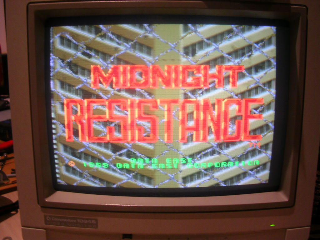
Anyway the seller said it worked fine except there was no sound, well not quite, when powered up it was clear that the video was missing the blue signal,
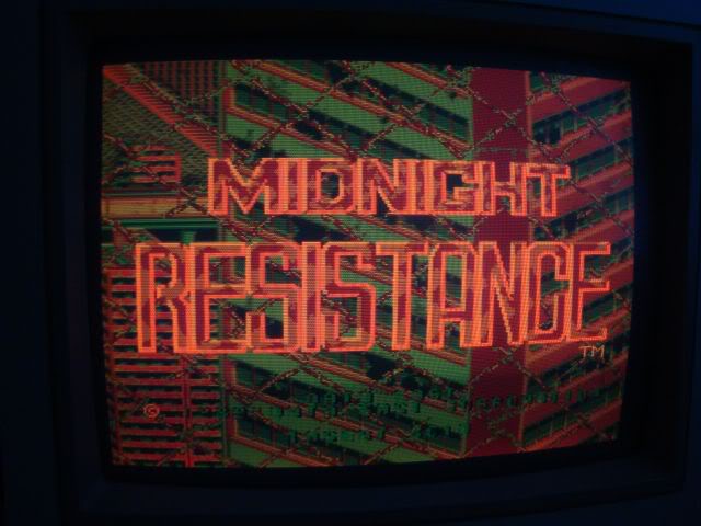

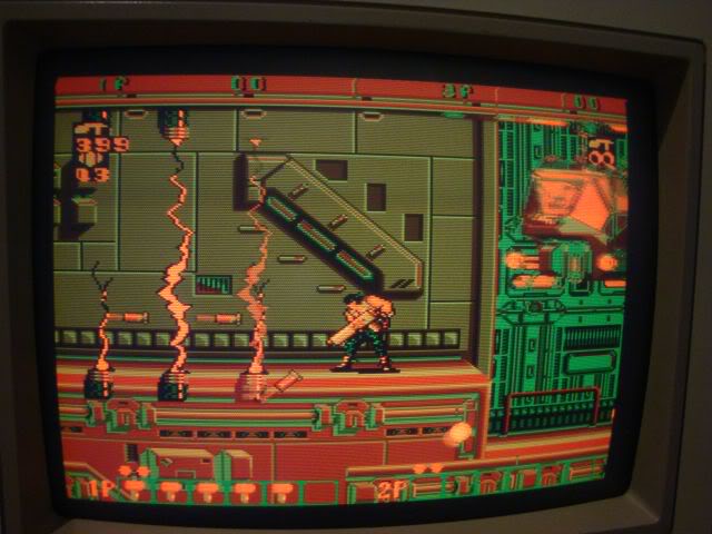
Originally thought it was my test bench jamma loom playing up as its getting very unreliable but poking the scope at the jamma edge connector showed that green and red were happily buzzing away but blue was silent. I visually followed the track back to NB1 (one of three - the other two pass the red and green) and then used the continuity meter to buzz around the nearby chips, pin 7 of a 74LS174 which was silent on the scope.
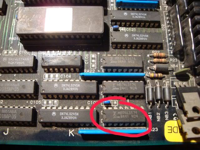
It was a Fujitsu chip, and these are often known to die by losing internal connectivity to a pin. The simple test is to piggy back a known good chip on top of the original. If it has died by losing a pin the piggy backed chip will light up that leg, and in this case the graphics were instantly fixed.
You can see the piggy backed chip circled in red.
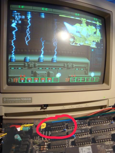
Piggy backing is not a guaranteed test tho, in fact in some circumstances it can result in the piggy backed chip being destroyed, but for F branded chips with missing outputs its always worth a go. In fact my piggy backer chips tend to be F brand chips I have suspected as faulty and de-soldered only to find that they are ok, will never put an F back on a board as they are so flaky, they make for good piggy backers though as I don't mind if they get zapped.
Anyway - I left piggy backed chip on and moved to the sound issue only to find that the speakers would sometimes crackle and sometimes not, I also got a lot of issues with the gfx as I was moving the board around, the red channel would flicker and the screen would lose sync. Turns out the JAMMA connector needed a good polish, it didn't look too crusty but a rub with brasso removed all the instability issues. The speaker hiss was then constant and the volume pot crancked it up and down so the amp section was also fine. I did a quick ESR check on the electrolytics but they were all good. When I powered it back up again I got the gunshot sound when coining the board up. Its possible that the sound issue was just a badly oxidised jamma connector but it seemed unlikely. I could get the coin up noises, and the "erk" noises as the enemies were hit, but no music or other effects, eventually the sounds stopped totally and I could never get them back for more than a second or so after that. In fact when the dipswitch was set to attract sounds on the board emitted a long tone until powered off, it never made another noise so I assumed the sound section was crashing long before I could coin it up. When attract mode sounds were off the 1st time it tried to do anything was on coin-up so that would explain why I could get a burst of sound out of it.
As the sound CPU on these boards is a surface mount chip I started off looking at the easier option of the TMM2063 - the sound RAM for the audio CPU, the address line inputs looked nice and clean but the outputs were a real mess...
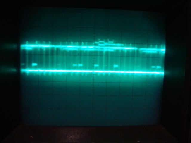
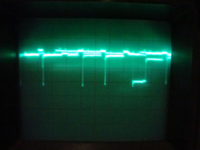
...signal voltage very unstable, no clear distinction between logic high and logic low. Usefully enough there were other TMM2063s on the board that were involved with the game execution itself so I could poke the scope at the outputs of those chips, clearly they were ok as the game was running. The outputs of the others looked nice and clean...
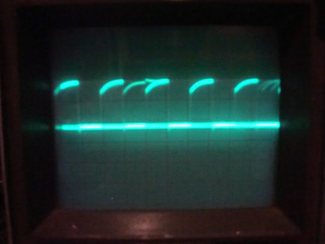
...so the chief candidate was indeed the sound SRAM.
Fired up the de-solder station and whipped out the 74LS174 and the TMM2063.
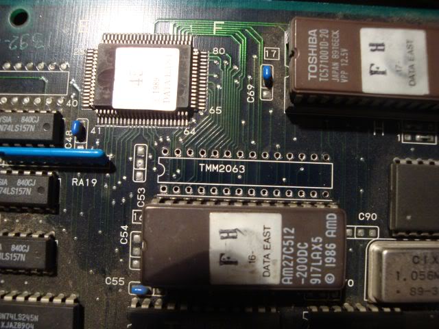
The TMM2063 failed the read write test on my eprom reader so I dug out a scrap board and de-soldered a Sony CXK5864BSP-10L chip which is a pin for pin compatible chip. How do I know this? The first thing to do when trying to find a replacement is to find a RAM chip that has the same number of pins as the one you are trying to replace, then google for the data sheet and compare the description. Both chips were described as "65536 bit CMOS SRAM organised as 8,192 words by 8 bits", then double check the chip pin outs are the same. Ignoring the fact that some manufacturers label their data pins as D0-D7 and some as D1-D8, and the same for the A pins you usually find they are totally compatible, the only other concern is the speed of the chip, which is denoted by the last number of the chip name eg CXK5864BSP-10L is a 100nSec chip, -70 would be a 70 nSec, -60 as 60nSec etc etc. If you don't have a collection of scrap boards then it gets a bit harder as you have to find a vendor then google what they are selling, you can't start with the simple eyeball conclusion that if it doesn't have the same number of pins it can be compatible.
I also de-soldered a Hitachi (i.e. bulletproof) 74LS174 chip and soldered it into the board, I tend to fit machined pin sockets for RAM chips if I can, firstly to save the SRAM chip from another blast of heat and secondly to future proof the board. The logic chip will probably last another 20 years, the SRAM chip is far less likely to so sockets save the PCB from another de soldering and make the board easier to repair too.
Dropped in the SRAM chip and fired her up, the graphics were perfect and all sound effects were back

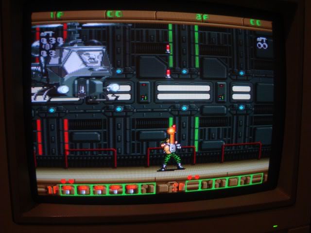
Mmmm Midnight Resistance....
A nice quick fix this one, judging by the state of the label tied to it that says "faulty" this board has probably been borked for many many years.
Board 2
Snapped up another faulty Midnight Resistance board recently, seller said the board would boot and give a blank white screen, but that the sounds were working and he could hear the game playing in the background.
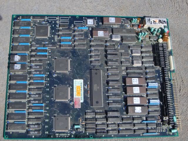
When the board arrived I gave it the old eyeball check and an empty chip socket stood out like bollocks on a bulldog,
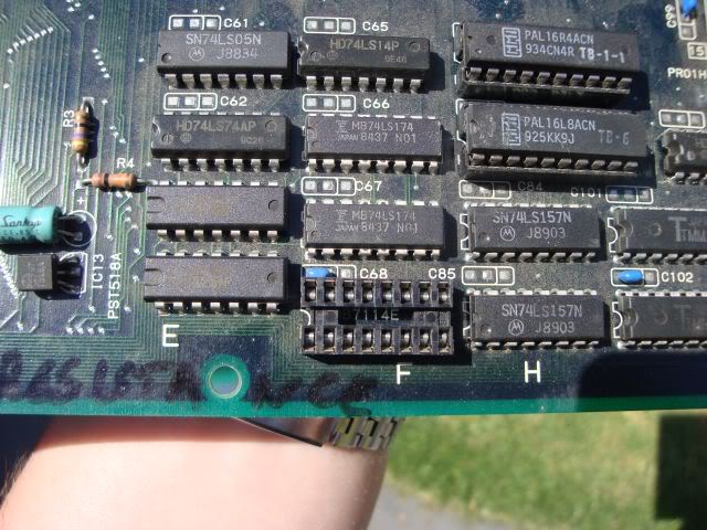
As did the fact a D880 power transistor had been snapped off.
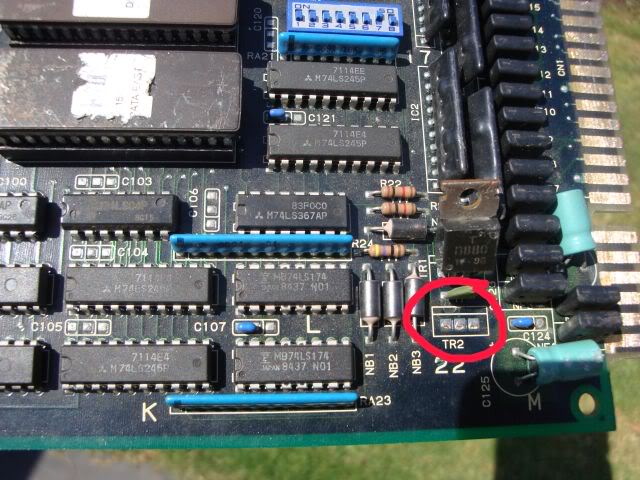
Sometimes you do get empty sockets on boards but each wasted socket cost someone a few cents so its not common on dedicated game boards (Capcom CPSx and Sega System16/18/32 often do have blank sockets depending on the game).
Anyway I have a couple of other MidRes boards so I knew what chip should be in that socket, and could borrow one to get this board up and running. The transistor wasn't a problem, its emitter was tied to pin 8 on the JAMMA edge connector, which is not used in the standard spec, but the MidRes manual says this is used for the coin counter, basically the transistor is there to provide a high current pulse to the mechanical coin counter, so its absence was not likely to be an issue.
Was a bit annoyed with the seller though, as the game clearly was not running, no sounds (just amp buzz ie amp was good) and the scope showed the 68K CPU was doing nothing, it shits me boards arrive in a different faulty state to how they were described in the sale. I actually went back to the ebay photo to see if this was the actual board on sale, could make out the missing chip and the texter writing on the amp heatsink so its clearly the one he meant to sell.
Anyway with the borrowed MB7116 PROM in place I got a screen of crap, sometimes coloured, but usually just black and white, board still wedged tho.
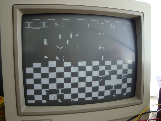
Went over the CPU again with the scope, it had volts, a healthy clock and the reset pin was high (i.e. CPU didn't have the handbrake on) - all good! However the "halt" pin was low, meaning the CPU had crashed, pretty much anything that causes the CPU to get scrambled or corrupt instructions will cause a crash and that could be anything like track damage, bus logic failures, bad RAM or bad ROM. The board is in very good condition with no signs of track damage, also no flaky F 245 or 273s across the CPU buses. So I started to dump the ROMs and compare with the MAME set. There are 4 27c512 ROMs near to the CPU which contain the program code, the first three tested fine, the fourth also tested fine, but only after I fixed what I found as I removed the chip from its socket. Without this pin the 4th ROM has no power so its not surprised the program code was corrupted.
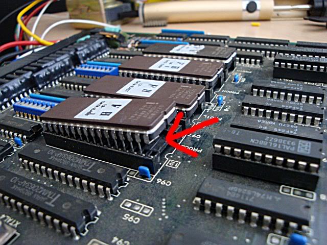
The game would boot and run after this was fixed, sound an all. Pulling the PROM out again gave back the fault the seller described, blank coloured screen but audible signs the game was running. It seems that the seller had tried to fix this himself, dumped the ROMs, found them to be OK and slapped them back in and sold the board.
Even though the game was now running it was clearly not well, half the screen was covered in white squares and there were odd fragments over the screen. Its hard to see in this photo but most of the gfx outside the white squares are fine and scroll correctly.
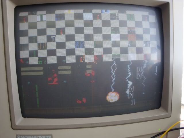
Everything was also upside down, mainly due to a dusty dipswitch that didn't work too well until it had been flipped a few times, on a subsequent reboot it decided to unflip the screen for me.
I went round the board with the scope looking for bad RAM, the sound RAM outputs looked horrible,in fact similar to the RAM that caused the fault on my other MidRes board.
All the other RAM looked fine, actually the program RAM looked a bit rough too but its not affecting the board. One pair of TMM2063 chips seemed to be involved in the fault, their outputs looked very regular (somewhat too regular) and shorting between two of the data lines on the chip RA12 at B9 caused some of the tiles to vanish and be replaced with gfx tiles that were correct.
Watch the green "I" in the white block
Normal
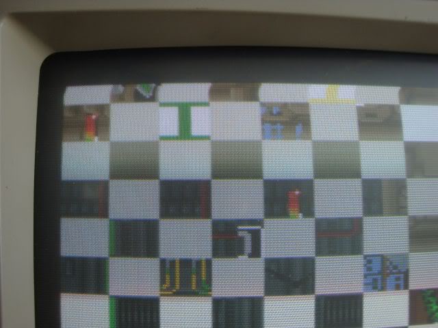
Shorted - the right gfx data appears..
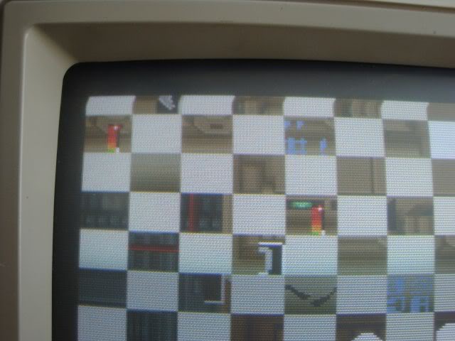
I desoldered both the gfx SRAM chips, and also the sound RAM, but all three passed the TMM2063 tests on my VP-280 reader/tester. So I soldered in 6x14 pin sockets (slim 28 pin sockets are not easy to find and not cheap, but a pair of 14 pin sockets end to end work perfectly and 14 pins cheap and easy to find). Fitted one chip back in the gfx pair and one of the old gfx ones into the sound section and booted the game.
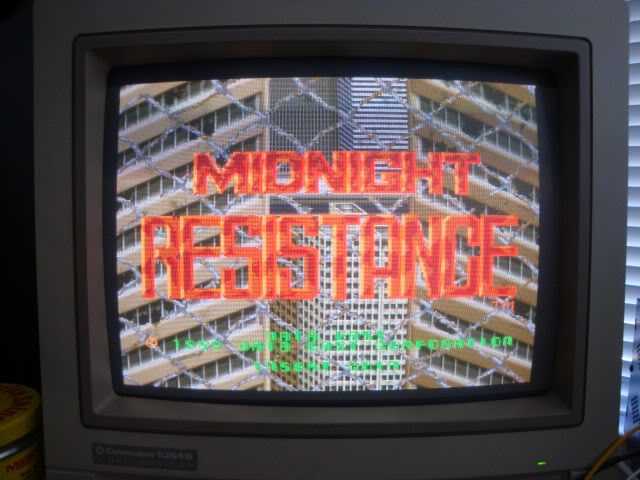
This should be the data east logo, the colours are right at least.
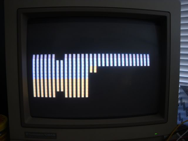
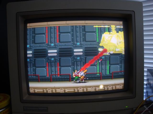
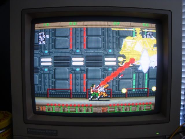
The game runs, no crap overlaying the game, but also all the "info" was missing, ammo count, number of keys collected, lives etc etc. Presumably the rubbish shown before was that info overlay system doing bad things.
I had put one of the original gfx RAM chips into the sound section earlier to see if its output was better than the chip that came from there (it was a bit), so I had the old sound SRAM chips on the desk. I dropped that into to the empty gfx SRAM slot to see what the effect would be, to my surprise the effect was that it fixed the game. I was expecting a similar fault to re-occur, in fact when I put each chip back into its original position I really did expect to see the same fault return, but it didn't.

Unlikely as it seems, somehow the violence of being desoldered followed by a test in my tester has cleared the fault in the SRAM chip. The outputs are no longer "too regular for my liking" and I can get similar faults to the original by interrupting the data pins now.
Will leave the original chips in the new sockets for the time being, if they play up again they will be binned.
The only other issue I have is finding a replacement for the 7411 PROM, but other than that shes fixed!
Board 3
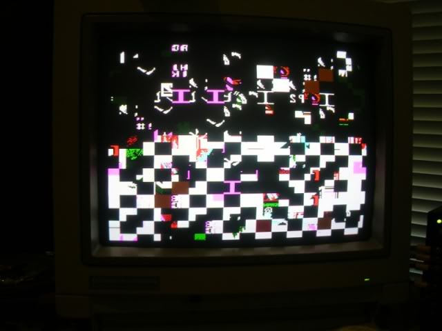
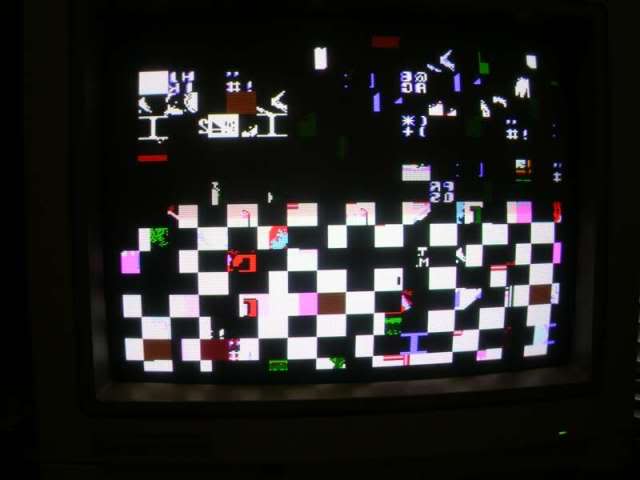
Got a couple more faulty Midnight Resistance boards recently, this one did this on power up, totally frozen screen of rubbish and a gentle two tone warbling noise from the loudspeaker.
The board itself was in pretty good nick, one wrenched cap..
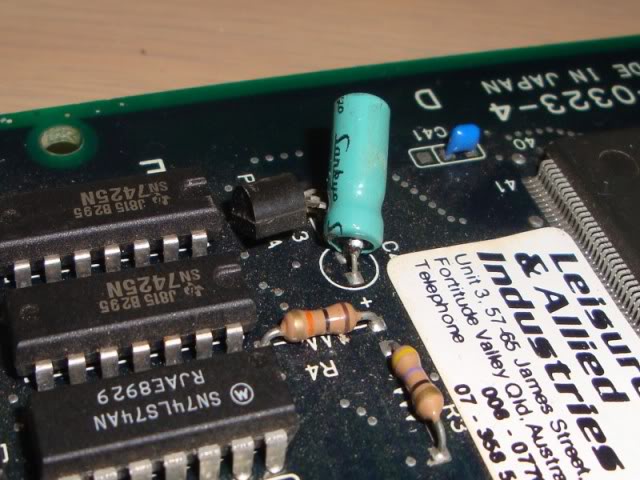
...and the carcass of a previous inhabitant in a rather webbed up corner.
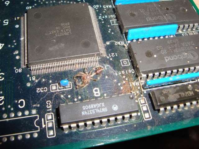
First off I fixed the cap, sometimes these are involved in the reset system on the board but it was a fair way from the 68000 so not that unlikely, plus the reset pin on this board's CPU was stable in "not reset".
Having fixed a few of these now I knew that the screen of crap is what the board does when it is missing all or half of a bank of RAM comprising two TMM2063 chips at 11K and 12K ..
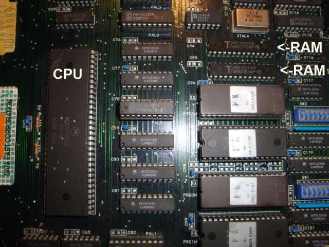
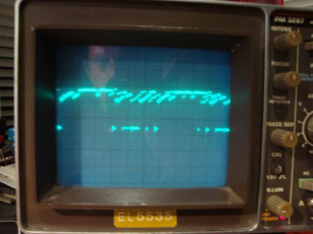
So I pointed the scope at the output of the two RAM chips and it was crap on some pins and awful on others.
So I desoldered both chips and put them through the SRAM test for TMM2063s on my EPROM reader. One could not be written to and the other gave an error saying the D6 and D7 pins were missing, so no longer connected internally it seems. What was odd was that one pin on the SRAM chip had been cut and soldered back in place, this is a common test trick to isolate a pin without removing the chip. You cut the leg off leaving enough of a stump on the chip to solder up the cut later.
So I fitted some machined pin sockets and a couple of Sony CXK5864 chips from a scrap board. Fired it up again and got the same fault.
So I pointed the scope at the address bus for that RAM pair, which it shares with 2 EPROMs and 2 mask ROMS, a few of the lines looked pretty knackered too..
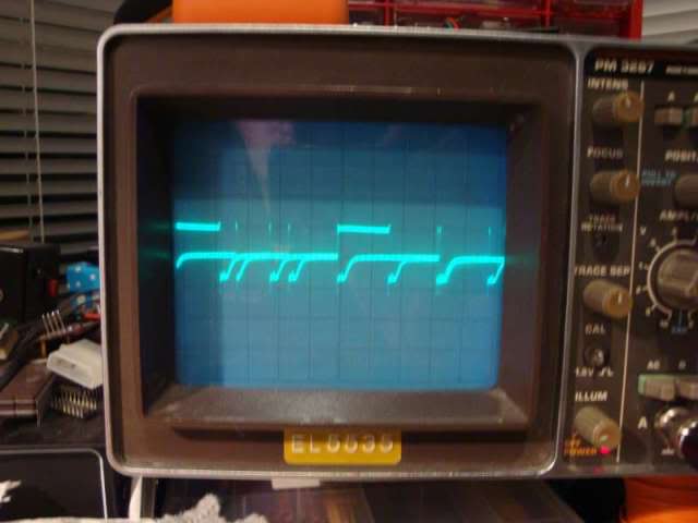
Have seen this pattern a few times before where the bus transceiver chips either loose the oomph to drive the downstream chips from logic 1 to 0 or the downstream chips are faulty to the extent that they take more grunt to drive them. Often chips will actually pass tests out of the board but the original system on the board is too weak to drive them. I pulled all 4 ROMs, read them and they checked out against the MAME set, proved they held the write data but not that the chips were really in spec. Also pulled the new SRAM chips out again and pointed the scope at the address lines on the now totally naked bus, the same wrecked signal was present. Traced it back to a 74LS245 at K21, its inputs were clean, but some of the outputs were in the state in the above photo. Replaced that chip, and the address bus lines all looked healthy, so I put the ROMs and the RAM back in and powered it up.
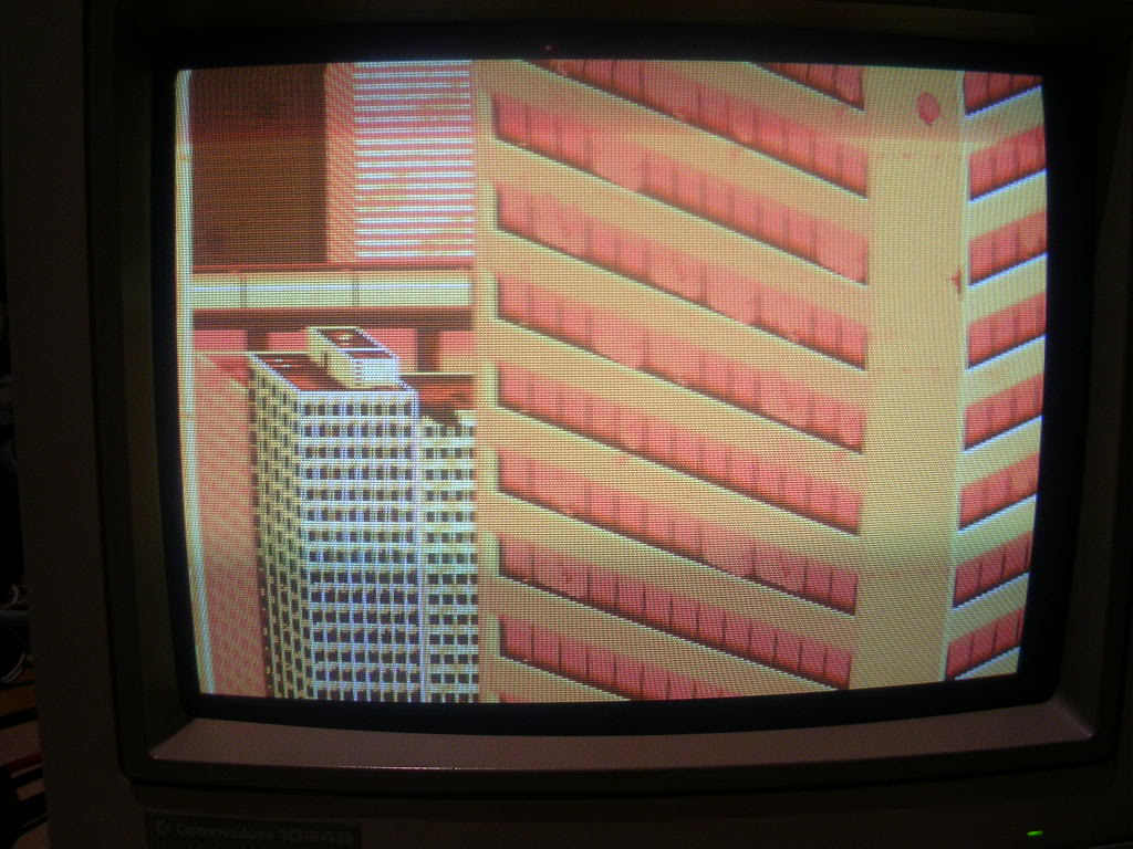
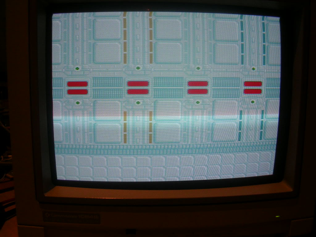
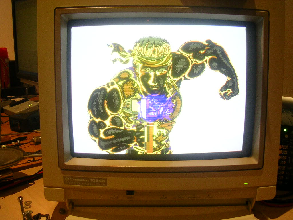
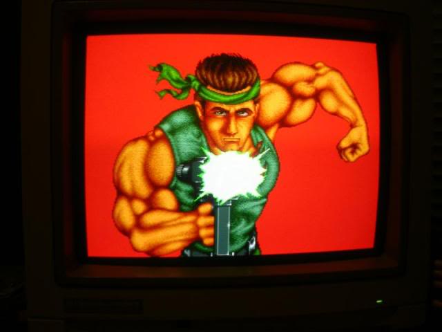
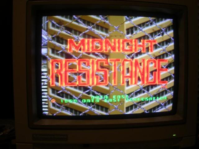
The game booted, but there was a problem, when MidRes boots it should show the following screens and then go into the title screen for 15 seconds or so, and then into the game demo.
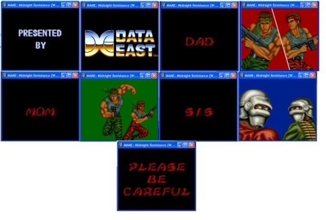
However this board showed a black screen for 10 seconds, then showed the split screen with the two fighters on the red background, then black again for 5 seconds, then the two fighters on the green back ground for 5 seconds, then black again etc. Every screen with text, plus the Data East logo was missing, I was only getting screen 4, 6 and 8, plus the delays while the others should be on-screen.
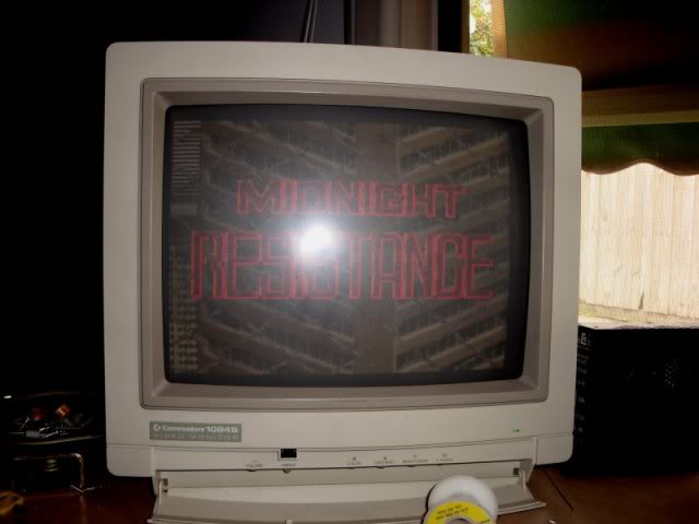
Once it finally got to the parallax scrolling splash screen all the text was missing, the "Data East Corporation 1989", and the flashing "insert coin".
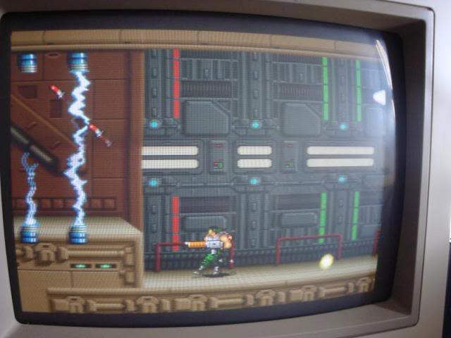
In the game all the ammo, keys collected and lives left logos were also missing.
I knew from previous boards that all this is stored in 2 ROMs 4 and 5 at the rear of the board. On some MidRes boards most of the gfx data ROMs are soldered in, but ROMs 4 and 5 always seem to be socketed, sometimes they are actually EPROMs, its this pair that differ from the US, WORLD and JAPAN versions of the game, so socketted to let Data East change the versions on their stock as demand required. Anything text related is stored in these eproms and processed via another pair of TMM2063 chips at B8 and B9. Poking a scope at the EPROMs showed some decent signals and the RAM outputs looked clean. The only way to be totally sure was to de solder them and test them off the board, they both were working fine. Back to scoping around the ROMs address lines showed something that looked odd, a few of the address lines were tied low. These traced back to a pair of 74ls273s at B11 and B12, the outputs looked fine but the inputs were pretty messy. To cut a long story short the 273 inputs were outputs from the 160 pin surface mount custom at B3 and for a while it looked like the board was going to be scrap. I dug out a working MidRes and compared the signals coming from its custom and they looked identically messy to this board. I decided to pull ROM 4 and 5 out of that board to see what it did with the ROMs missing. On my board the lack of these ROMs made no difference, but on the working board all I got was a white screen with the game playing without a display. Clearly on a working board the overlay data really is overlayed, as all the data pins on the ROMs were tied high via resistor networks when the actual ROMs were missing it would appear to the game as if the ROMs contained all 1's, which would be full RGB at all points of the screen - whiteout!!!
So I went straight for the PROM at F22 knowing when that is missing you get a blank screen. I had already tested that PROM in another board by the way. I found that pin 13 (an output) was doing nothing, yet if I shorted pin 12 and 13 together I got this...
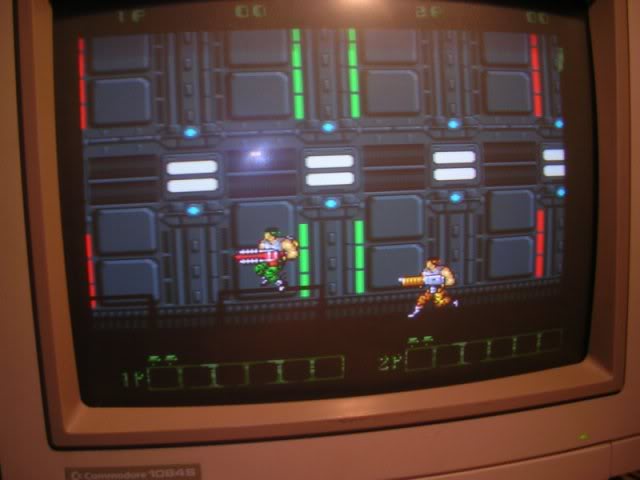
...the overlay was there faintly and somewhat corrupted. Tying pin 12 low briefly got me this...
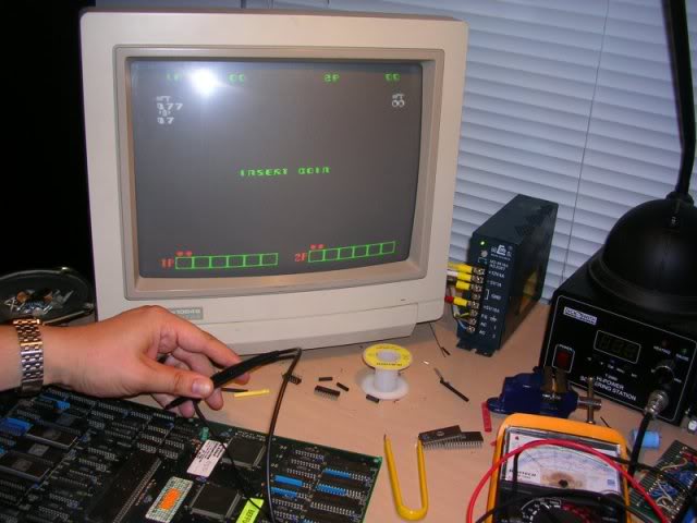
.. the overlay in its entirety, but nothing else.
By comparing the working board to the faulty one I could see that one of the address lines was doing nothing on the faulty boards prom, but not as low as all the other logic level zero signals were, this one was about a 1.5Volts higher and not very stable. Traced this back to a 7425 at E22. All of this chips inputs were healthy but its output was stuck, piggybacking a 7425 from a scrap board...
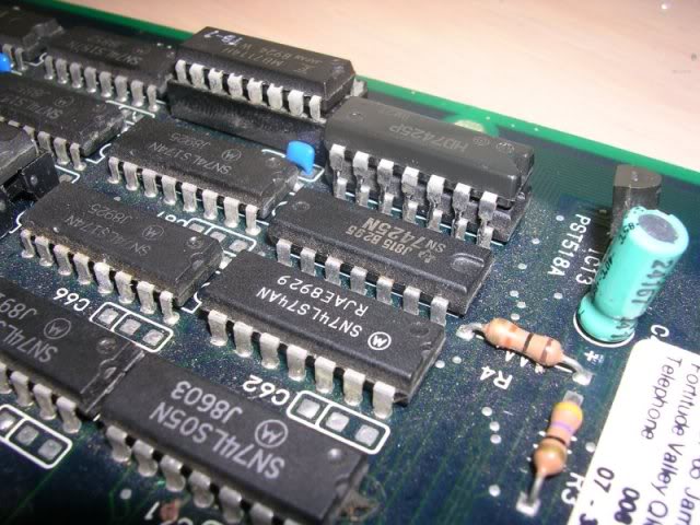
.. fixed the issue!
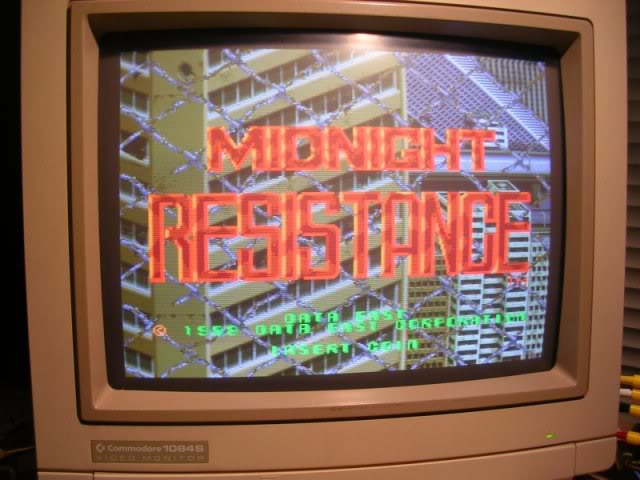
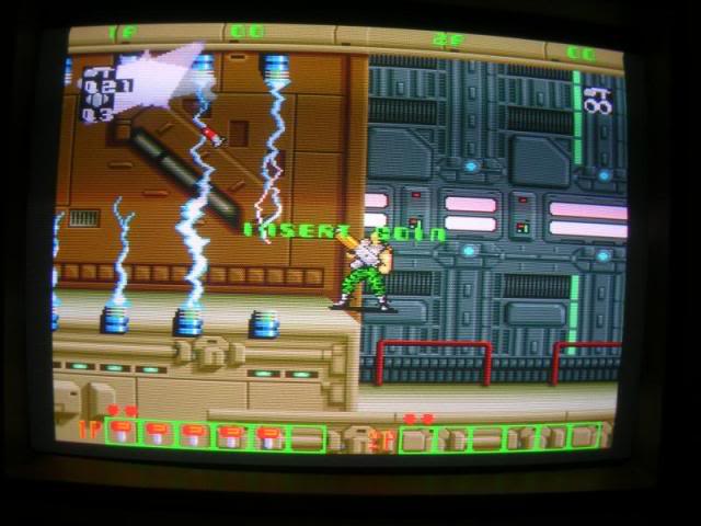
Ironic that the chip causing this troublesome fault was located right next to the bashed cap I replaced at the outset.
So I desoldered the old 7425 and soldered in the piggybacked on and the fault stayed gone.
Took the board to my cab for a test blast and found fault number 3!
The rotary control from the twisty joystick (you turn the joystick shaft to determine which way the character points his gun) wouldn't always work. Sometimes you could get half way through level 1 before it would just stop working, and other times it wouldn't work at all. The game was still running and you could do everything except aim. Thankfully this was a simple fix, the pins poking through from the ferrite beads in the path of the rotary control inputs were rather long and some had been bent together and were slightly touching. Straightening these out fixed the last problem, can play the game all the way through without a single problem now!!
Board 4
OK I promise this is the last Midnight Resistance repair log for a while, I have no idea why so many faulty ones have popped up over the last few months, haven't seen any workers for sale anywhere.
Anyway - this board was mint, absobloodylutely mint, could have been made yesterday, not a scratch on it. The only thing I could see that worried me was 2 blacked pins on one of the custom LB0072 custom chips...
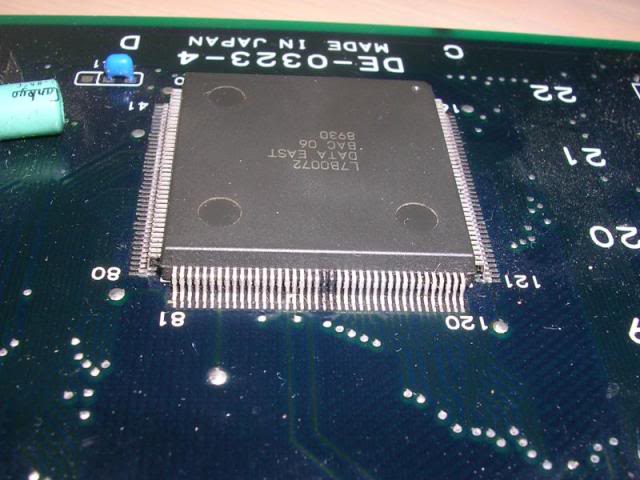
...this is a sure sign that something dropped on the board while it was running and shorted these pins out, OR more likely, someone trying to fix the problem jammed their probe between the two pins. When this happens its really a case of luck as to how much damage you can do. If someone is stumbling around probing stuff and they bridge two data pins then this wouldn't do much but if one of those pins was +5V and the bridge gave that a nice easy path to ground then the PSU will gladly step up to the challenge and supply all 15Amps of current at its disposal along that path, until something nominates itself as the fuse and burns out, usually instantly with a puff of smoke and a bad smell, incidental if you do manage this (we have all done it once or twice) its always useful to make a not of where the smoke came from, often a track on the board will have gone from stone cold to red hot and vaporised in a fraction of a second, the burnt out gap can be tiny and hard to spot, so follow the smoke!!! The burnt out section is not likely to be the only fault but at least if you know where you buggered it you can fix it and move on, if you have no idea where it was then its going to be a struggle.
Anyway I had a feeling that the custom was toast and was preparing to have a go at replacing a 160 pin surface mount chip as I have another Data East board as scrap with these ICs on it.
The game booted ok, but some of the gfx were not right.
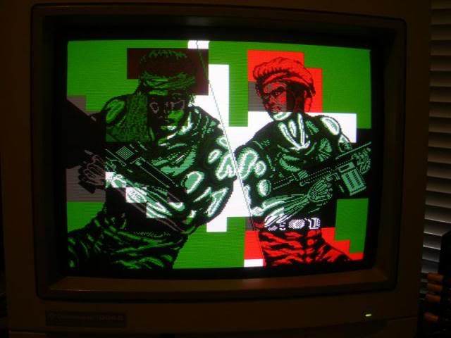
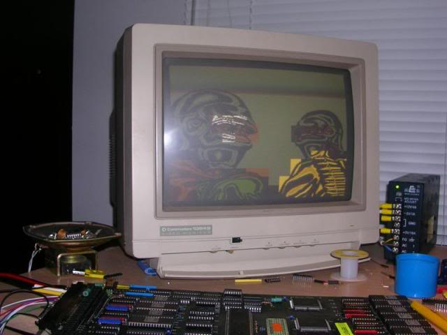
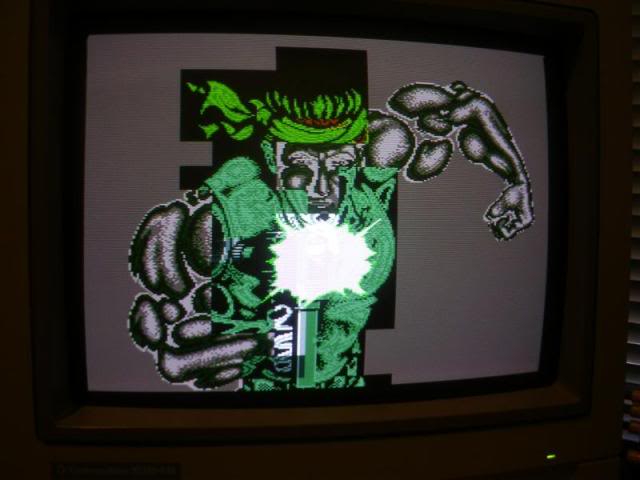
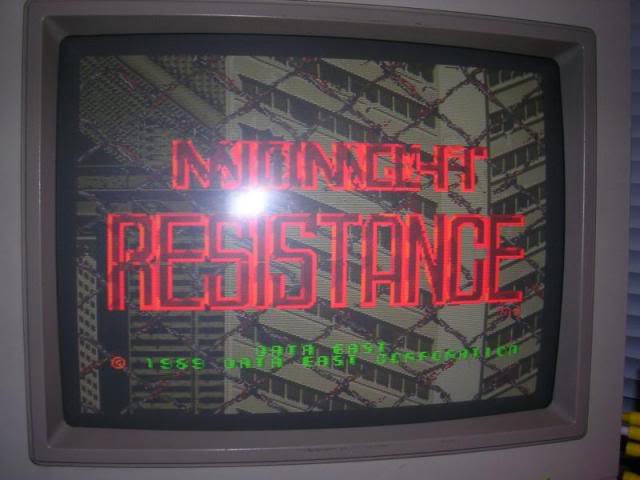
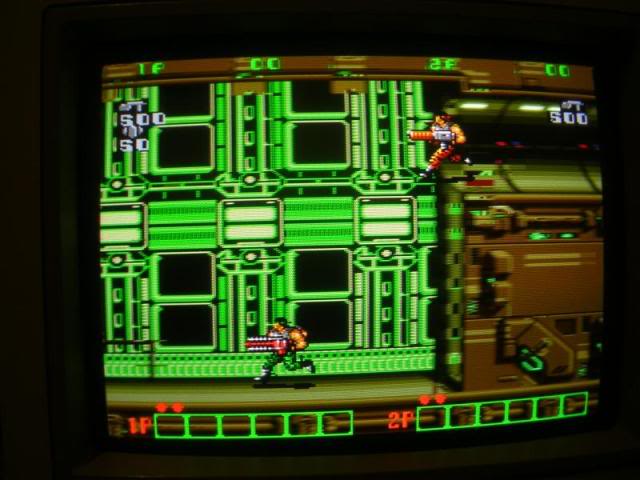
The in game looks OK but the backgrounds are missing a lot of the colours other than green even tho it actually looks pretty good! Not overly surprising seeing as these LB0072 customs control banks of graphics EPROMs ( I worked out its pinout from a couple of schematics of other games - should doco it for here ).
First step when troubleshooting graphics issues is to check the ROMs, usually they are socketed and its quick and easy, even if it is a bit boring on boards with lots of ROMs. The gfx roms on this board were all mask ROMs, is ROMs that were made with the data already in them, etched in with a photo resist mask that defines the internal structure which defines the data. The were all TC541001P chips, which my reader didn't support, however they are pin for pin compatible with 27C100 EPROMs odd pinout really) so it kinda did support them. Anyway - they all dumped fine except for ROM 9 and ROM 10, both showed up as having blown address pins, #9 was missing 2 pins and #11 was missing 9. Both were ROMs associated with the suspect custom chip.
So I did a check on the board to see if there were any shorts to either ground or 5V on any of the ROM pins, (to make sure the board wasn't going to destroy any chips put into these sockets) burnt new copies of #9 and #11 into a couple of AM27C100 chips using the data from the MAME set, dropped the chips in
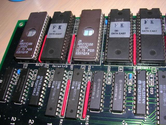
and fired her up....fixed!
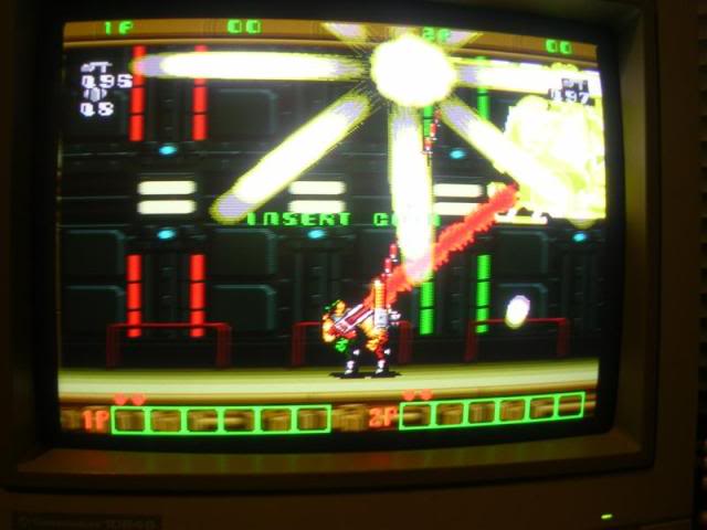
Am lucky that custom wasn't bad considering the violence it was subject to, surface mount customs are generally very hardy beasts anyway thankfully. Plus it would have been a shame to have to scuff up such a mint board tho I admit I was up for a go.
Right that's my last MidRes board, seriously I don't have any more....... Editor: Yeah right....
Board 5
Repairer: Womble
Forum Thread: Midnight Resistance PCB Repair
Brace yersel folks, this ones a long'un
Have to split over two posts as toooo many photos.
Got another couple of Midnight Resistance boards in a batch recently, one in a very bad shape, and one that looked pretty good. Both were stone dead, the good one looked like a fair prospect as there was minimal track rot unlike its partner.
Hooked it up on my test bench and got nothing, blank dark screen and no sound. On the solder side there was some scuff marks and some dodgy looking tracks but everything buzzed through ok except for one obvious blown one which I jumpered with some hookup wire. It's the rightermost track of the 4here, looks kinda roasted.
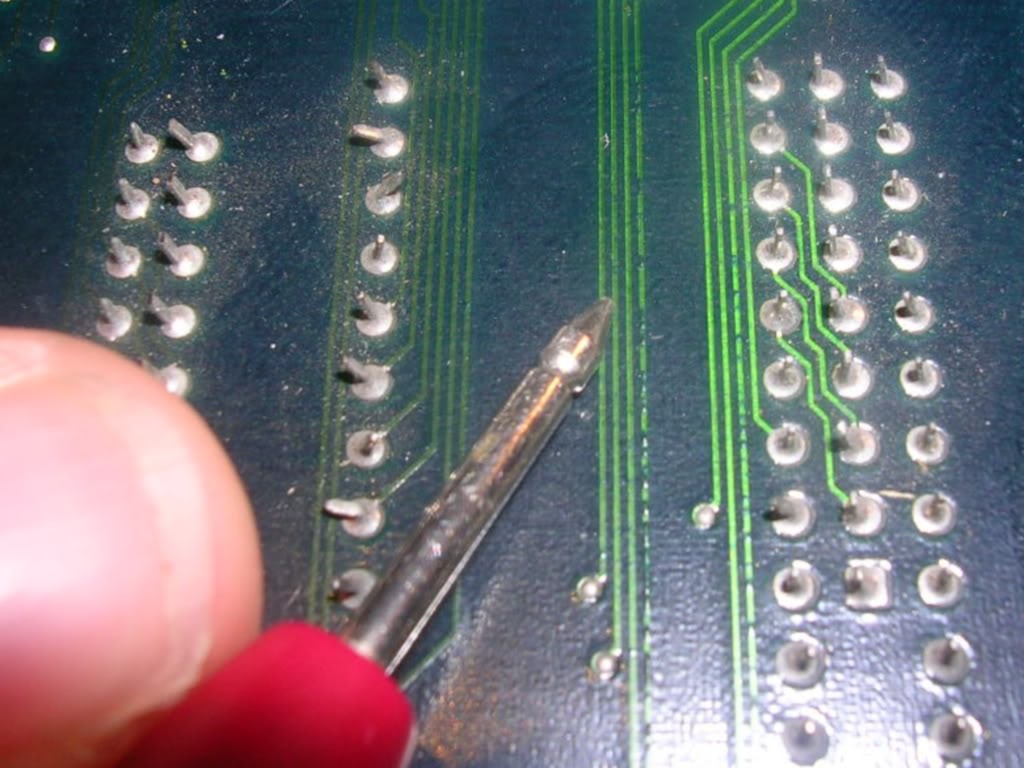
However the damage was a long way from the CPU, RAM and program ROMs so it was unlikely to be the cause of a dead board.
Going over the 68000 cpu with the scope proved the CPU was getting clock, it was not in RESET or HALT, it was just doing nothing, the address and data buses were silent. The most likely candidate in such cases is the RAM, but as the ROMs were socketed I verified those first. So, out with the SRAMs, both TMM2063's which are very common failures, both were confirmed dead by my ERPROM tester so sockets went in and a couple of equivalent chips were installed, Sony CXK5864s.
When powered up again, the scope showed activity on the two buses, but I still had a totally blank screen and no sound. Poking the scope at the JAMMA edge connectors showed I had sync but nothing on the RGB lines. Having fixed half a dozen MidRes boards I know my way around them quite well and the RGB channel output comes from a pair of 74ls174 chips at L21 and L22, usually Fujitsu brand and usually totally hosed. They did not disappoint, both chips were missing all their outputs and replacing these lit the board back up. I also replaced the final Fujitsu chip on the board, a 74ls367 that also tested as dead when removed.
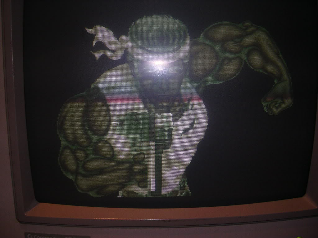
I now had various screens from the attract mode showing up, as well as the backgrounds which scrolled around as they should. At this stage I also removed the sound section SRAM, another TMM2063 and another dead chip. Fitting a socket and installing another CXK5864 did nothing to restore the sound though. There were two remaining TMM2063 chips at A10 and A11 which deal with the foreground text and icons, again both these chips were dead so replacements were installed in sockets, which didn't actually change anything at this point in the proceedings.
By this point I had a house full of jet-lagged guests so managed to only grab a few brief anti-social periods in my toyroom, and the next time I got to look at this board it royally shat itself. Upon power up I was greeted with a very loud sound of zapping chippery, roasting tracks and a slow whine from the speaker. The board was dead again. I was fairly confident that most of the noise had come from one of the fat surface mount custom chips too, so it got slung back in the box it came in on a plume of colourful language.
I was pretty annoyed that I had wasted decent machined pin sockets on it at this point as they are next to impossible to get back off a board as their legs are so chunky. So after a few weeks I decided to see how bad it was, I hadn't actually seen any smoke or smelt any burning but whatever had happened had sounded pretty violent.
When hooked up again I could see that the address and databuses were running still, but the screen was once again blank. Several TMM2018 SRAM chips were now getting stinking hot too, one of a pair (B14) by the background mask ROMs and both of the screen pallet TMM2018s at J21 and J22. These were getting so hot that there was no chance they were going to pass any tests so I simply snipped the legs off each chip and desoldered the pins individually. As I was not convinced the board was worth losing any more decent sockets on I fitted a couple of tatty salvaged dual wipes and a couple of 6116 variant chips. This restored the display but the colours were even worse than before.
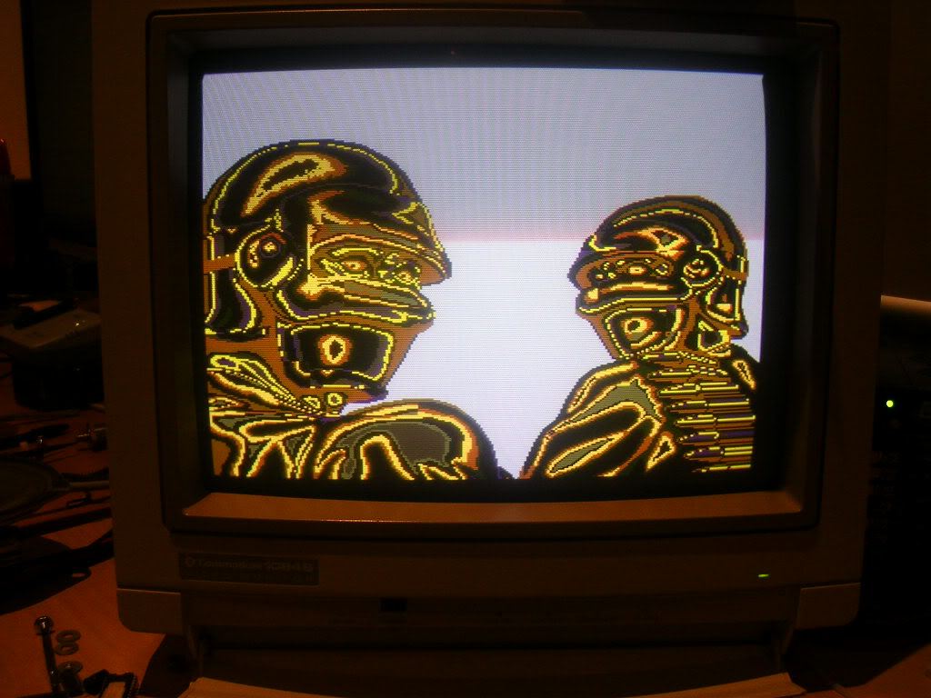
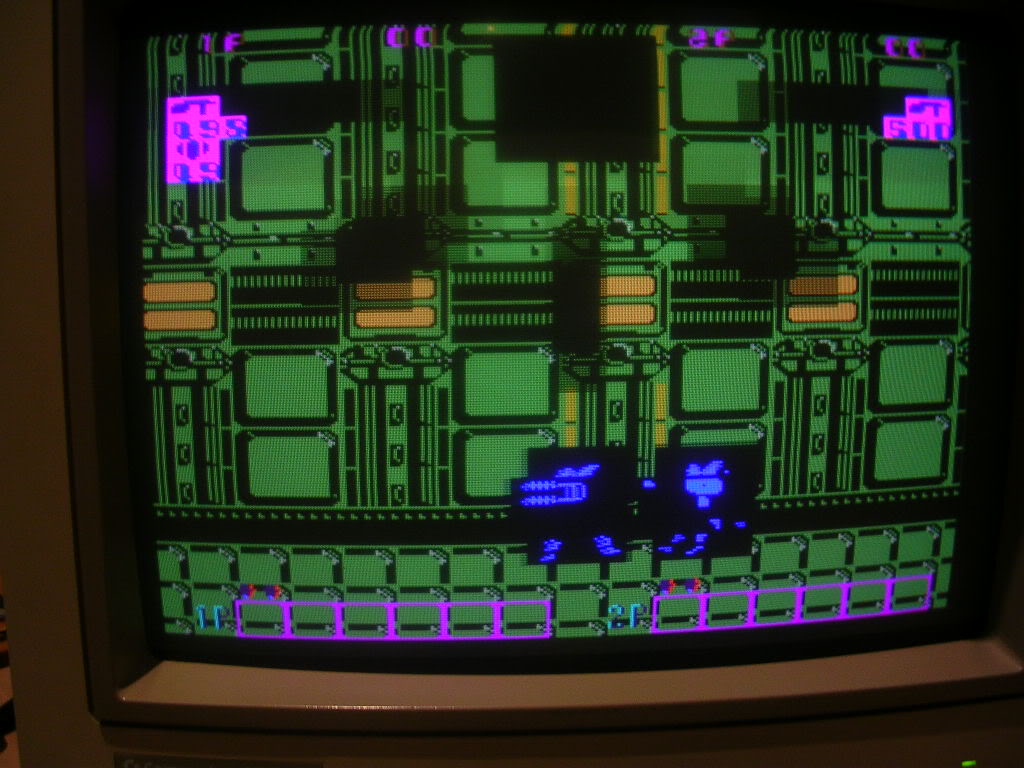
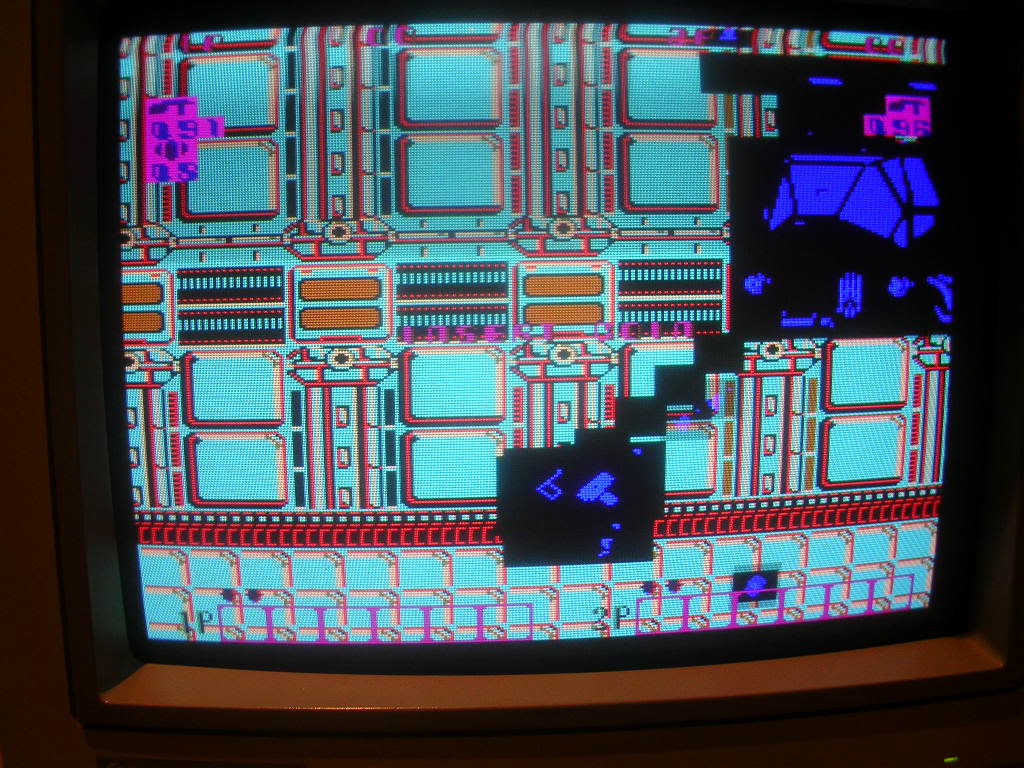
I ignored partner chip of the overheating one as I didn't have any more non-decent sockets to risk, so moved on to the other missing screen elements, the foreground text/icons, and the sprite field. The data for these layers are mixed into the gfx data stream by two 7425s, the foreground text and icons by the one at H22 and the sprite layer by the one at H21. Both of these were dead, healthy inputs but no output. Replacing them both restored their respective layers, however the colour issues seemed to be getting worse, the background colour choice was fairly random, sometimes green, sometimes grey.
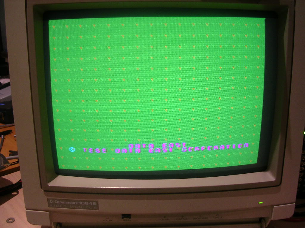
The background data was also partially missing as the RAM in this section was half missing, half dead which made the colour issue even more severe.
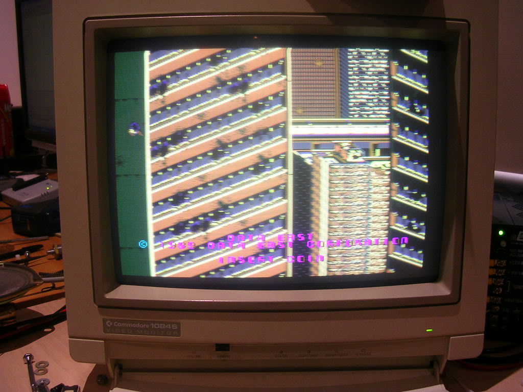
I felt like I was getting somewhere again so I removed the TMM2018 that hadn't turned itself into a heater and dropped in two sockets and two new 2018 chips at B13 and B14. The backgrounds started to look a little better but now the foreground was rather dark and gloomy.
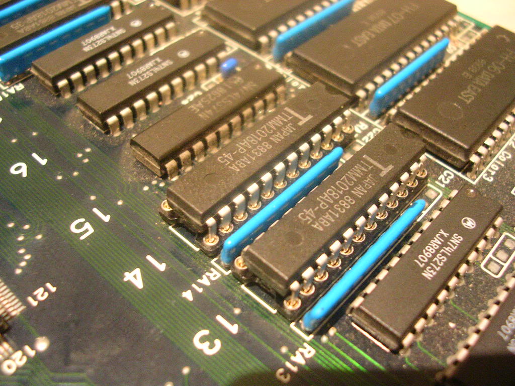
So I started to poke around the palette SRAMs chips I had replaced and found the problem, address lines A0 to A4 were silent and held low, these traced back to a pair of LS157 chips that had clearly been destroyed when the SRAM fried. Replacing these...
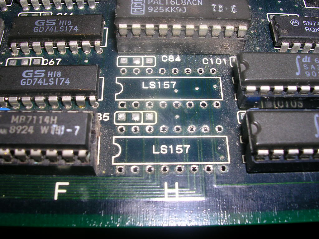
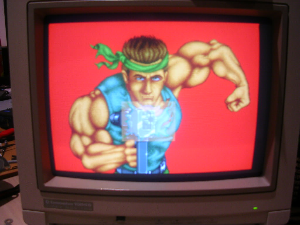
...finally fixed the colour fault once and for all.
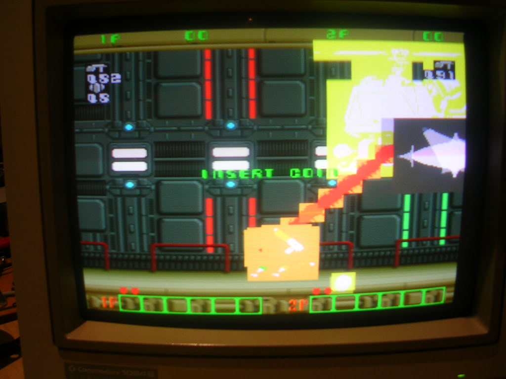
The sprites were still not well tho..
.. and there was a chip in the sound section that was starting to get extremely hot.
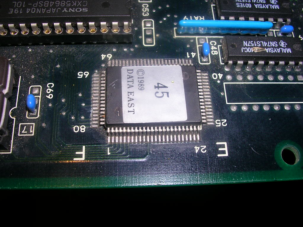
So hot in fact that it was starting to smell, and as I didn't want the shite roasted out of the board I decided to focus on the sound for a while. Identifying the chip was fairly easy, a quick look in the MAME driver showed that the sound section had two CPUs, the small OKI 6295 by the amp and an HuC6280 made by Hudson Soft - the same CPU as used in the NEC TurboGrafx 16! Finding the pinout for that was a struggle but I finally found a text file version that confirmed it should have 80 pins and a clock signal on pin 10, which fit the bill for the chip that was cooking.
Finding a replacement was also easy, I had planned on pinching the one from the rotten MidRes board but that one also got roasting hot when powered on. I ran up a working MidRes board to confirm that the chip does not normally run that hot so both boards I had got had suffered the same failure. In the same batch these boards came in was an utterly filthy, battered and corroded Tumblepop, also by Data East, from the same year and also with a HuC6280 driving the sound section. Data East seemed to have bought batches of these CPUs ground the markings off and labelled them all as "45" as Tumblepop had the same sticker on the HuC as MidRes did. The Tumblepop board was also totally dead but the HuC did not overheat.
The only complicating factor was this was a surface mount chip, time to crack open the ChipQuik and lose my SMD virginity!! QuikChip is basically a very low melting point metal alloy designed to allow the removal of SMDs without expensive hardware, I bought some ages ago but had never needed to use it until now. You apply flux to the chip legs and melt in a length of the alloy, the original solder dissolves and due to it's low melting point it take so long to cool enought to harden that you can get all the legs molten at once, the chip then can then be slid off, and it works...
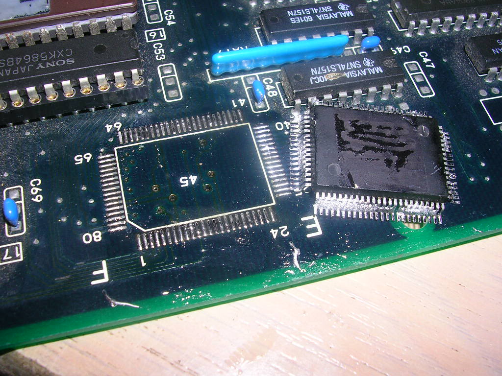
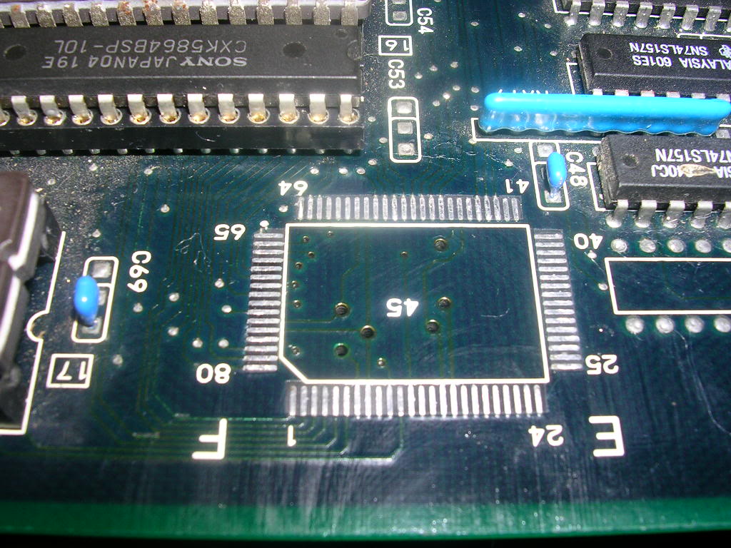
Leaving the board in mint condition.
The donor chip got the same treatment...
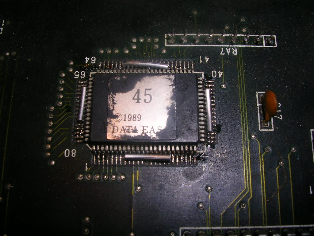
...and was just as easily removed. Cleaning up the chip for reuse was straight forward, the QuikChip stay molten for so long you can just tap the chip on the desk and it mostly just falls off. A quick run over with the desoldering iron removed the rest.
Soldering it in place took a while until I changed to a chisel iron tip and used enough flux, then the new joints almost fell into place.
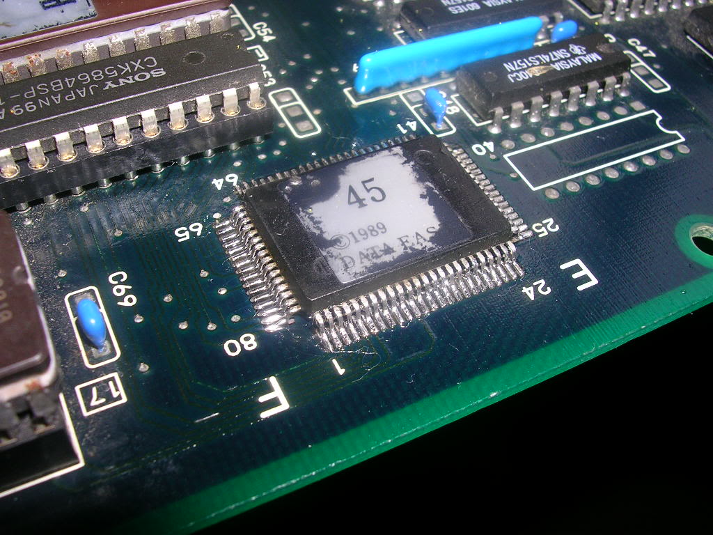
After going round with the meter checking for bridges, and fixing the two I couldn't see by eye, it was time to power up again.
No smoke, no sparks, time to coin up.... GUNFIRE, start the game...
..Music! Sound Effects! Wooohooo! At this stage I was one happy Womble!
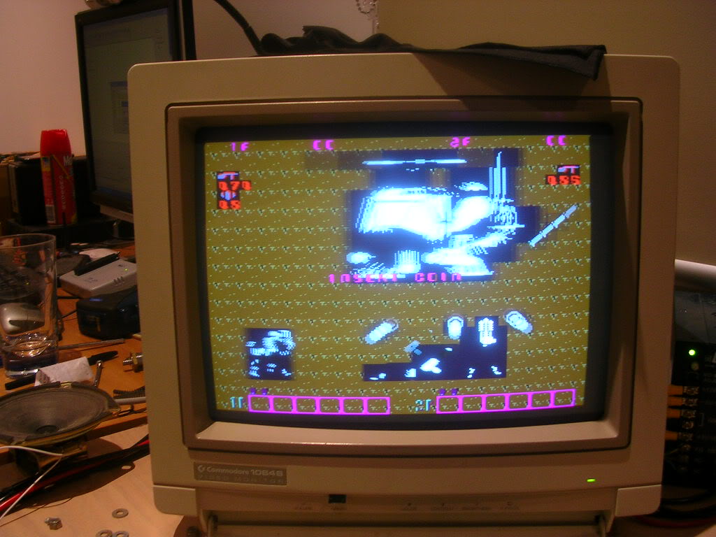
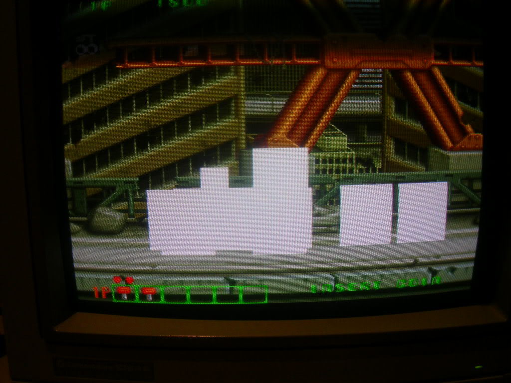
The only thing between me and a working board now was the sprites. I have seen this fault effect on a few board, large blocks of colour floating around where the sprites should be, blocks far larger than the sprites themselves, this equals missing data, large lumps of data. The sprites are really blocks of screen real estate where an "on" pixel takes preference over anything else on the screen, therefore it is in the foreground, any "off" pixels do not get displayed and the background data is left unchanged. When you get large blocks like this you have far too many on pixels, basically large lumps of sprite data are no longer actual data, just lumps of FF in the ROMs. Or actually probably not in the ROMs, the ROMs often are no longer really ROMs, just a chip with jammed output pins which gets read as FF at all loci. The board is still driving the ROMs correctly but they are no longer doing anything, but board still takes their output as if it was good data, even if that data never changes. So you get the large blocks drifting around.
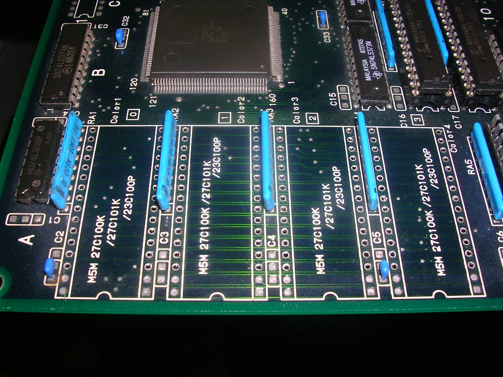
On this board the sprite data lives in 4 mask ROMs at A3, A4, A5 and A6, their outputs were all active and all their inputs looked good. The fault was either the ROMs themselves or due to upstream chippery being damaged. Everything looked ok upstream but the large 160 pin "MXC 06" custom chip was a bit of an unknown quantity. I decided to give the solder side of the PCB another going over by eye in this area first and the first thing obvious thing was the burnt track I had repaired at the outset. The track was the A15 line to the sprite ROM bank, and although it was now bridged with hookup wire it was clear that this area of the board had been shorted out somehow and that track had taken the full force of the power supply before it nominated itself as the fuse and vaporised in various places. This is the exact sort of treatment that ROMs really do not like, although whether it was a dying mask ROM that cause it or not I will never know. The track went to the last of the 4 mask ROMs, called "03' and then hopped to 02, 01 and 00. So I desoldered the directly connected on and put it in my eprom reader. I had to make a small adaptor so it could be read as a 27c100 chip. Mask ROMs are often shorter than their EPROM equivalent as the data is built into the ROM as it is made, there is no programming step so no need for a programming pin. Thankfully this board comes in a few variants, some with normal EPROMs and some with mask roms, which just sit in the same socket set back 4 pins. All I had to do was use an old socket and bend the 5V pin out of the way and connect it in what was empty space on the reader socket, but where the power pin of a 27c100 would be.

The chip dumped perfectly and came back as being a Midnight Resistance ROM ff03 - slightly disappointing. Chip 02 was desoldered and again read fine, however the dump was not recognised at all, and subsequent dumps all had differing checksums, a duff ROM!! The remaining two ROMs, 01 and 00 had been completely destroyed though, my reader flagged most of the pins as "out of spec"...
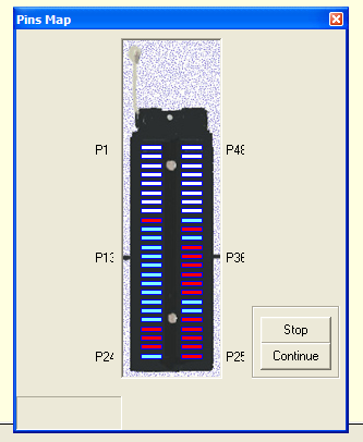
...and the chips just gave totally empty reads, all FF which is exactly what I was hoping to see.
With all four off the board...
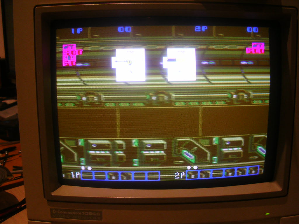
... I powered it up, this shows what you get with completely blank sprite data, all the data lines are held high by the pull-up resistor networks as there is no ROM data to pull them down., so all bits in the sprite area are on and take preference over the background for all RGB channels giving bright white blocks.
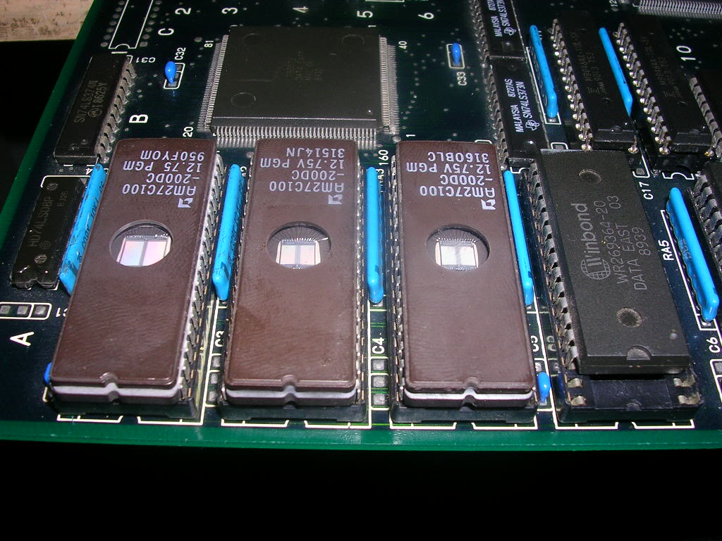
So, as the board can take either the shorter 28 pin mask ROMs, or 27c100s (32) pins all I had to do was clear the solder from the previously unused 4 holes per chip, fit some sockets and drop in three 27c100s containing the MAME data and the one remaining mask ROM that rhad survived, which you can see set back in its socket slightly.
Time for some power....
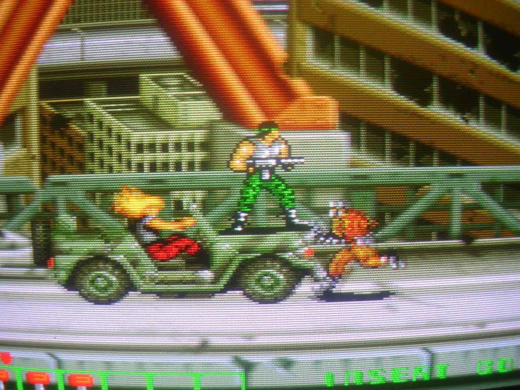
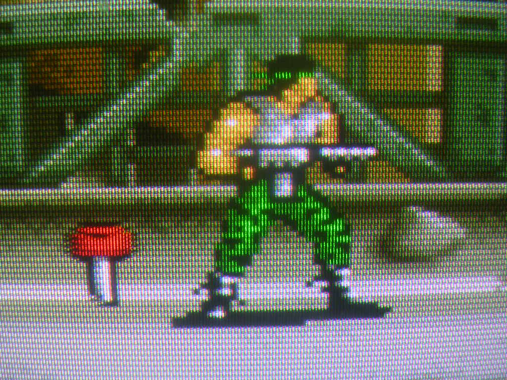
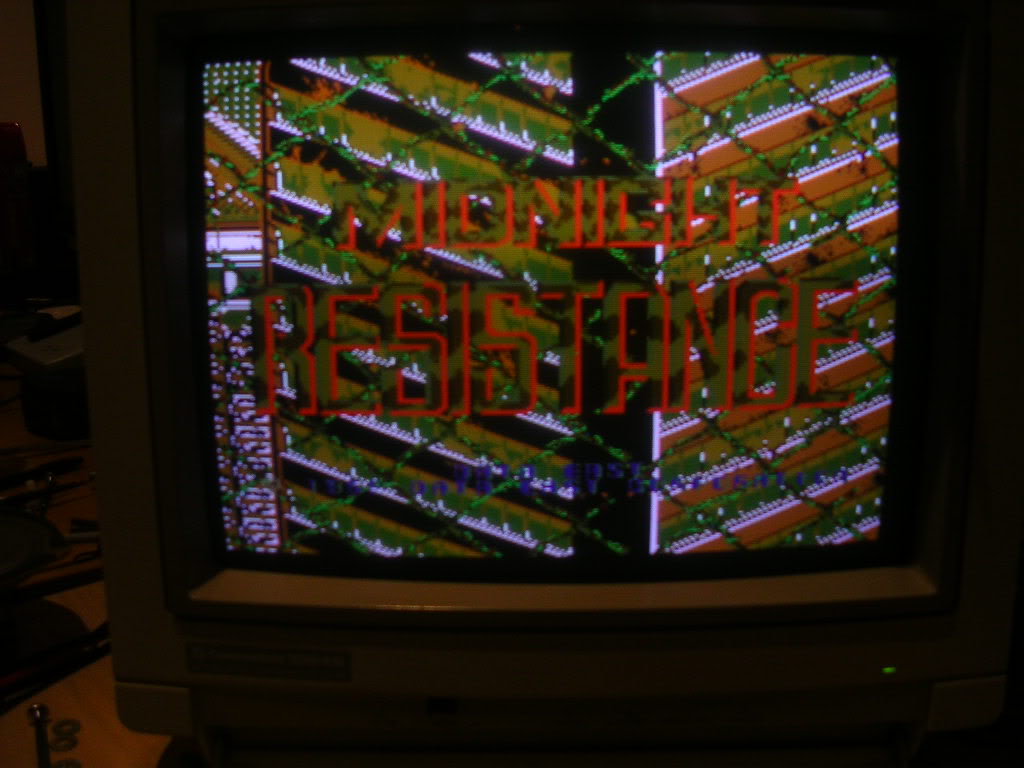
... I love it when that happens
Board fixed!
