PCB Repair Logs Q*bert: Difference between revisions
mNo edit summary |
mNo edit summary |
||
| (One intermediate revision by the same user not shown) | |||
| Line 4: | Line 4: | ||
<tr class="> | <tr class="> | ||
<td colspan="2" class="" style="text-align:center;">[[Image:marquee_qbert.png|200px]]</td> | <td colspan="2" class="" style="text-align:center;">[[Image:marquee_qbert.png|200px]]</td> | ||
</tr> | |||
<tr class=""> | |||
<th scope="row" style="text-align:left; white-space: nowrap;">Manufacturer</th> | |||
<td class="" style="">[[PCB_Manufacturers_Gottlieb|Gottlieb]]</td> | |||
</tr> | |||
<tr class=""> | |||
<th scope="row" style="text-align:left; white-space: nowrap;">Year</th> | |||
<td class="" style="">1982</td> | |||
</tr> | </tr> | ||
<tr class=""> | <tr class=""> | ||
| Line 11: | Line 19: | ||
<tr class=""> | <tr class=""> | ||
<th scope="row" style="text-align:left; white-space: nowrap;">Pin Out</th> | <th scope="row" style="text-align:left; white-space: nowrap;">Pin Out</th> | ||
<td class="" style=""> | <td class="" style="">[[PCB_Pinouts_Q'Bert|Q'Bert]]</td> | ||
</tr> | </tr> | ||
| Line 96: | Line 104: | ||
Fix: Going through the data sheet of the SC-01 I read something that caught my eye. | Fix: Going through the data sheet of the SC-01 I read something that caught my eye. | ||
Quote Originally Posted by SC01 Datasheet MCRC (Master Clock Resistor-Capacitor) This input determines the internal master clock frequency. Select E C values for 720 khz to achieve standard phoneme timing Connect this input to MCX when using internal clock, ground when using external clock. | Quote Originally Posted by SC01 Datasheet MCRC (Master Clock Resistor-Capacitor) This input determines the internal master clock frequency. | ||
Select E C values for 720 khz to achieve standard phoneme timing Connect this input to MCX when using internal clock, ground when using external clock. | |||
NOTE | NOTE | ||
Latest revision as of 07:00, 7 February 2013
Q*Bert
 |
|
| Manufacturer | Gottlieb |
|---|---|
| Year | 1982 |
| PCB Image | Reserved |
| Pin Out | Q'Bert |
Repairer: Arcade King
Forum Thread: Q*Bert PCB Repair
All you get when you fire the board up is scrolling horizontal lines. No sync.
I had to make a simple H/Vsync to csync adapter so I could work on the PCB on my test rig.
PCB has battery corrosion around the bottom left hand corner that covers about 1/4 of the bottom of the board about 2/3's the way across and about 1/4 of the way up along the edge connector. Removed the battery and sprayed the board with isopropyl alcohol to prevent further damage.
General probing.
Other bad IC's 74ls157 D2 through to D10. Replaced all 9 IC's. some were dead others were on the way out so best to replace the lot. El Salvador dated 8136
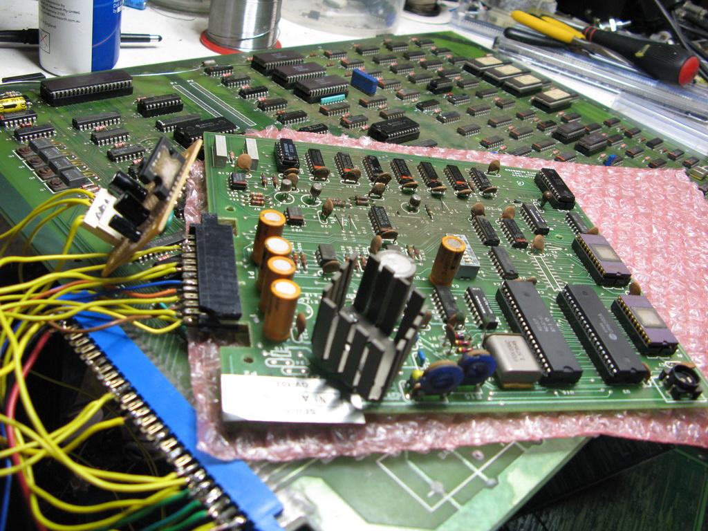
74ls374 @ D11 pin 16 stuck high 74ls244 @ D12 pin 3 was stuck low. 74ls86 @ D16, E15 and F17 74ls273 @ E16 These IC's have to do with the background generation. I put in sockets because they were in the battery acid damaged area. After removing the IC's I cleaned the plated through holes the best I could using a fibre glass pen then dropped a socket in.
Replaced 4118 rams @ E7 and E10-11 for Hitachi 4116's, the legs were basically about to fall off. 4118's are 1kx8 while 4116's are 2kx8. pin 10 (A10) is already pulled High so a simple drop in replacement. Also replaced 2 of the program roms for Hitachi ones to match the other 2 that were already on the board.
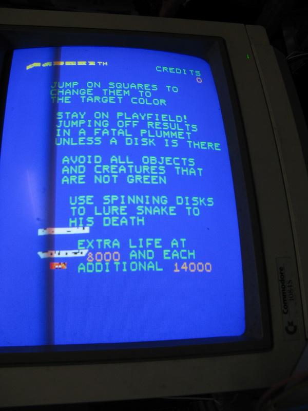
At this point I can see data there on my CRO but its just looping.. OK note to self Qbert has to have the test pin grounded for the game to run Game is running great except all the character graphics are squished up. (see pic)
Problem turned out to be a 74s161 timer @ H5 I used a 74ls161 in its place. Those 74S161's get far too hot for my liking. I'm going to replace the lot with LS which work just fine. (The bootlegs use LS)
Game board now 100% but the sound board is another matter, the board uses some funky voltages. I attached a step down transformer to the cab yesterday so I could test the soundboard but unfortunately all I got out of it was garbage sound. I've just ordered a pair of SC-01-A Speech Chips from Kevin at www.GameRoomRepair.com so I can eliminate the speech chip before I start tearing apart the sound board. It could very well be a voltage problem also but its always a good idea to have some of these rare IC's on hand. lets face it the sound is what makes Q*bert so special. I'll update the thread on the soundboard once I've received the IC's
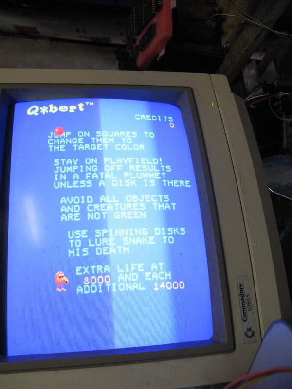
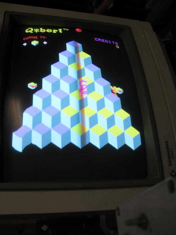
First pic is of the GFX fault the rest are of the game running 100% The distortion on the left is just a monitor sync issue. I cant adjust the sync on my C1084s without pulling the case off.


Just a quick update.
Decided to make myself up a quick bodgy backyarder Qbert to jamma harness so I could work on the sound board. I used a home made external AMP, the onboard amp needs 30VDC! I soldered the wire for the input to my amp on pin 9 of the qbert amp underneath the pcb.

I divided up the PCB into 2 sections 1 for speech and 1 for general sound FX.
The General Sound FX were completely dead and the speech is just garbled.
Probing around I could see the sound working for the general sound FX via the outputs on the 74ls75's at U8 and U8 but the output (pin 4) on the 1408A DAC was stuck low IE Boned. Luckily I have 2 scrap bootleg Qbert. While they are both missing the Speech chip circuitry they do have a single DAC on them for the general sound FX of the game.
FIX: Replaced the 1408A dac with a AM1408N8. All the general game sound is working again
I'm pretty sure the other DAC (U19) is fine because I can hear the garbled voices coming out the speaker. I will look over the speech chip circuit closer tomorrow but I suspect the speech chip is screwed.
If anybody knows a good source for these 1408A DAC's PLEASE let me know. I only have 1 left on the other bootleg. Any of these will do 1408A HA17408P AM1408N8
Had a small graphics glitch in the character graphics which developed while running the board for a few hours last week.
Problem: small flickering line on the right hand side of qbert and other character graphics.
Fix: Very easy to find. Touching the logic probe foreground roms address lines which increase the glitch specifically RA1 to RA4. Traced it back to a faulty 74ls379 @ K3
Just an update on the sound.
Got my SC-01-A's from Kevin but the speech is still screwed.
Problem: Speech is unrecognisable. Pitch of the sound is very low and long like its saying something far too slow. Fix: Going through the data sheet of the SC-01 I read something that caught my eye.
Quote Originally Posted by SC01 Datasheet MCRC (Master Clock Resistor-Capacitor) This input determines the internal master clock frequency. Select E C values for 720 khz to achieve standard phoneme timing Connect this input to MCX when using internal clock, ground when using external clock.
NOTE Varying clock frequency varies voice and sound effects. As clock frequency decreases audio frequency decreases and phoneme timing lengthens. Looking at the Q*bert sound board schematics to see what's in circuit on the MCRC and MCX pins we have a LM741, 1408 DAC and a couple of transistors. I socketed the LM741 and playing around with it I found I got correct sound or pretty close to it (but faint) by pulling pin 2 out of circuit. Pin 2 is connected to a variable resistor and pin 4 of the DAC which is the output. Replacing the 1408 DAC @ U19 fixed the voice so essentially both DAC's on the board dead luckily I had the 2 bootlegs with these on it. I'm relived the SC-01 on the board was ok now I have 2 spare A 7407 died along the way in this repair but replaced with a NOS 74ls07 Q*bert sound is fantastic to be sure! so 80's
Very happy camper my Qbert is 100% working now Joey has fixed the chassis I should be able to play it tomorrow.