PCB Repair Logs Pacman 2 1: Difference between revisions
mNo edit summary |
mNo edit summary |
||
| (5 intermediate revisions by the same user not shown) | |||
| Line 4: | Line 4: | ||
<caption class="summary" style=""><b>Pacman 2 in 1 Bootleg</b></caption> | <caption class="summary" style=""><b>Pacman 2 in 1 Bootleg</b></caption> | ||
<tr class="> | <tr class="> | ||
<td colspan="2" class="" style="text-align:center;">[[Image:Pacman2-1.jpg|200px | <td colspan="2" class="" style="text-align:center;">[[Image:Pacman2-1.jpg|200px]]</td> | ||
</tr> | </tr> | ||
<tr class=""> | <tr class=""> | ||
| Line 22: | Line 22: | ||
<p>'''Repairer:''' [http://www.aussiearcade.com.au/member.php/1-Arcade-King Arcade King]<br> | <p>'''Repairer:''' [http://www.aussiearcade.com.au/member.php/1-Arcade-King Arcade King]<br> | ||
'''Forum Thread:''' [http://www.aussiearcade.com.au/showthread.php/52-Pac-1-2-PCB-Repair Pacman 2 in 1 PCB Repair]<br></p> | '''Forum Thread:''' [http://www.aussiearcade.com.au/showthread.php/52-Pac-1-2-PCB-Repair Pacman 2 in 1 PCB Repair]<br></p> | ||
<br> | |||
<p>This was the pic of the board on the E-bay, Chris the guy who won it paid I think like 95 pounds for it or something.</p> | <p>This was the pic of the board on the E-bay, Chris the guy who won it paid I think like 95 pounds for it or something.</p> | ||
<p>Notice the Jamma adapter, it magically went missing when I picked up the board off JP.</p> | <p>Notice the Jamma adapter, it magically went missing when I picked up the board off JP.</p> | ||
<p>[[File:Pac2-1-broken.jpg]]</p><br> | <p>[[File:Pac2-1-broken.jpg]]</p><br> | ||
| Line 70: | Line 70: | ||
2532 Eproms used on these boards are very similar to 2732 pin out wise except for 3 pins. | 2532 Eproms used on these boards are very similar to 2732 pin out wise except for 3 pins. | ||
[[PCB_Repair_Index|Back to PCB Repair Index]] | |||
Latest revision as of 11:33, 14 August 2012
Pacman 2 in 1 (Bootleg)
 |
|
| PCB Image | Pacman 2 in 1 |
|---|---|
| Pin Out | Pinout |
| Pacman Board Theory | Board Logic |
Repairer: Arcade King
Forum Thread: Pacman 2 in 1 PCB Repair
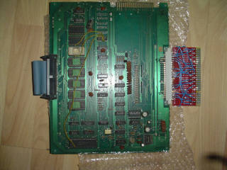
This was the pic of the board on the E-bay, Chris the guy who won it paid I think like 95 pounds for it or something.
Notice the Jamma adapter, it magically went missing when I picked up the board off JP.
Before we start
SBC=Sync Bus Controller
VRA=VRAM Addresser
The sync bus controller interfaces the external devices to the processor. The address and data bus are connected to the roms directly, but for ram and IO port access the sync bus controller gets in the way. An important thing to note is that the 6M* input to the SBC trails the 6Mhz used to generate the timing clocks by 1/3 phase, so the edge occurs during each level of 1H. The /CS line is asserted during a /MREQ with A14 high, during a non-refresh cycle (/RFSH high).
To handle interrupts, Pacman uses the I interrupt regiester to store the high 8 bits of the interrupt vector address and writes the low 8 bits to 0x00, which stores it in the register at U7.
During a mode 0 interrupt, /IORQ and /M1 are asserted, and the stored value is put back onto the data bus, and used as the low 8 bits of the of interrupt vector.
The VRAM addresser determines the address to be accessed by the video output circuitry based on the values of the horizontal and vertical timing signals. The address is enabled by /2H. When 2H is low, the CPU controls the bus. When 2H is high, the video generator controls it.
When /256H is high, normal screen data is being output. The low 10 bits of the VRAM address are determined by [128V, 64V, 32V, 16V, 8V, 128H, 64H, 32H, 16H, 8H]. The high bit is always 0, and the 11th bit is 4H, so that background sprite numbers are read on one cycle (4N), and the color is read the next (4P). 4V, 2V, 1V, 4H, 2H, and 1H are not used in the address directly, since they are not needed, since the sprites are 8x8 pixels.
The data addressed here is When /256H is low, the outputs are determined by whether 16H==32H==64H. If all three are euap, the address is [0, 4H, 64H, 64H, 64H, 64H, 8H, 128V, 64V, 32V, 16V, 8V]. This occurs when drawing either the score area or level area. The address is scrambled to use the screen ram area that is not used by the screen itself.
During VBLANK, the VRA addresses 4FF2-4FFD, where the motion object sprite numbers and color codes are stored. Note that due to the addressing, only 6 of the 8 sprite positions can be used.
Information was taken from Pac theory document attached.
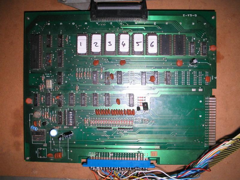
Its interesting to note that all 3 pac boards that I have had have all had the "PacGal" hack done. PacGal being the bootleg version of Ms Pacman. The hack consists of 5 2532's with a 2716 on the top board and 4 2716's on the bottom board. This is one of my favorite boards, the SBC and VBA are intergrated into the board itself so no rider boards,. There are 2 edge connectors, a 18 pin same pinout as the Pac 3 and a 24 pin connection.
When I made my harness I fired her up and was greeted with a blue screen. If you look closely you can see horizontal moving rectangles which are infact the characters.
The sound was also messed up, the music played but one channel was off key and all the sound effects were either not there or completly wrong.The amp on this board was getting super hot, this was a easy fix as it was just a bad cap at C27. If you touched the top of the cap it would make a huge scratching noise. I ended up replacing all the caps on this board, they all looked pretty old and nasty.
I was given some really bad advice on this board by a very dishonest operator which lead me to do a lot of unnecessary work to the bottom of this board. I found the real problem with my logic comparitor. When I was checking the chips with it I noticed when I placed it on the colour prom at 4A and tilted it back the maze would appear but it was all white. Replacing this prom fixed the graphics on the board.
The sound problem I traced back to another prom at 3M Rewired the Ms Pacman hack to the back of the top board so everything is hidden nice and neat.
Quite easy to fix this board, too bad it took twice as long as it should have. This was however one of the first boards I ever attempted to fix..
I tried the pacman 2 in 1 hack on this board but for some reason it would only play Ms Pacman and when I swicthed it to Pacman all you would get is a bunch a characters on top of one another in the bottom right hand corner of the screen. I firgured perhaps it had something to do with these bootlegs originally using 8 2716 to play Pacman, the original Paman board used 4 2532's.
I might go back and have another look at this, I recently fixed a board that is VERY similar to this one and the 2 in 1 hack worked!. I ended up settling for the Ms Pacman hack using 6 2532's on the top board( I had to steal one Eprom off my pacman 2 board), Character Eproms on the bottom board did not have to be changed as Pacgal is exactly the same.
2532 Eproms used on these boards are very similar to 2732 pin out wise except for 3 pins.


