PCB Repair Logs Legendary Wings Bootleg: Difference between revisions
Created page with "==Legendary Wings (Bootleg)== <p><table class="infobox vevent" style="width:22em;" cellspacing="5"> <caption class="summary" style=""><b>Legendary Wings (Bootleg)</b></caption..." |
mNo edit summary |
||
| Line 3: | Line 3: | ||
<caption class="summary" style=""><b>Legendary Wings (Bootleg)</b></caption> | <caption class="summary" style=""><b>Legendary Wings (Bootleg)</b></caption> | ||
<tr class="> | <tr class="> | ||
<td colspan="2" class="" style="text-align:center;">[[Image:marquee_legendary_wings. | <td colspan="2" class="" style="text-align:center;">[[Image:marquee_legendary_wings.png|200px]]</td> | ||
</tr> | </tr> | ||
<tr class=""> | <tr class=""> | ||
Latest revision as of 10:07, 5 September 2012
Legendary Wings (Bootleg)
 |
|
| PCB Image | Reserved |
|---|---|
| Pin Out | Reserved |
Repairer: Elgen
Forum Thread: Legendary Wings (Bootleg) PCB Repair
I have had this bootleg of Capcoms Legendary Wings on the table a couple of times, but that was before I owned a programmer, desoldering station, and a scope, so I had to give it up. But now I decided to give it a final try before scrapping it.
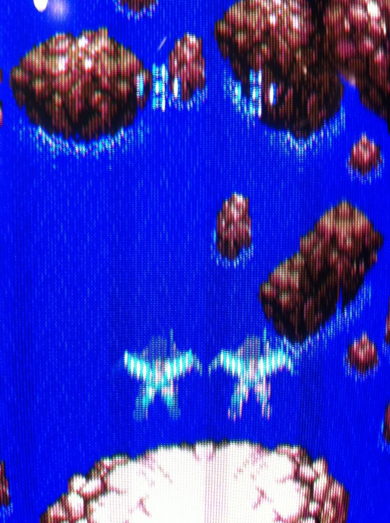
The problem was, that all sprites had blue stripes running through them in the direction of the scanlines and the game had no sound.
The board is far from prestine; it has a lot of scratches etc. Some broken tracks on the 2nd board was obvious with just the naked eye.
This pic is taken with a halogene lamp behind the board.
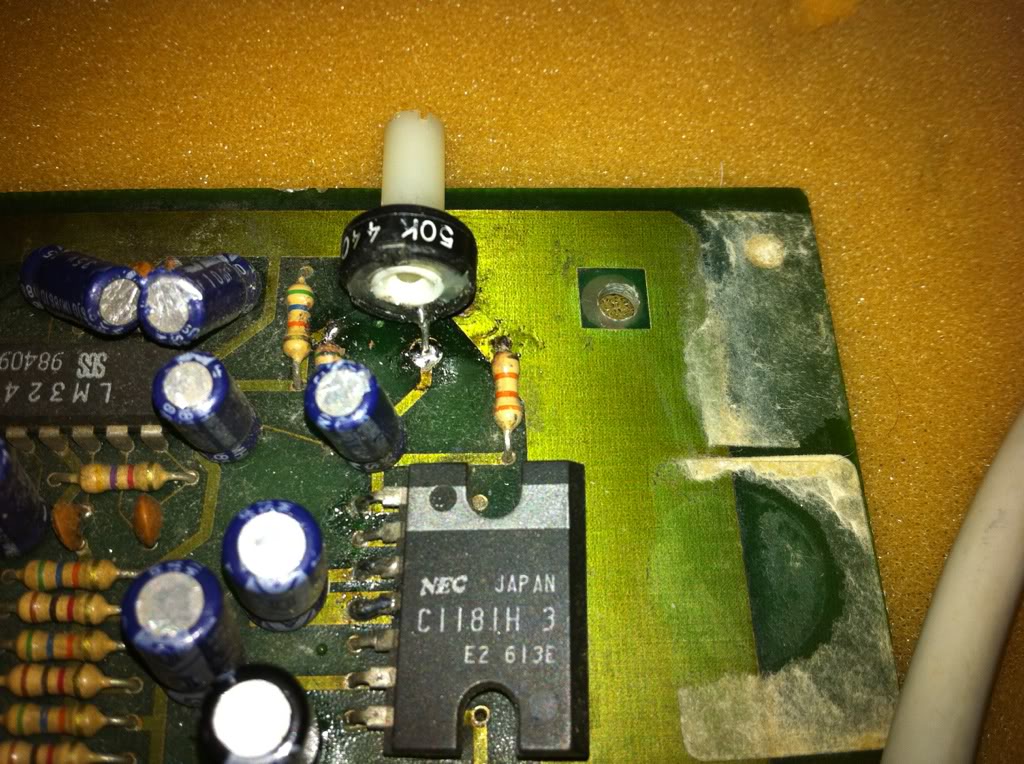
And for the sound it was pretty obvious what was wrong too.
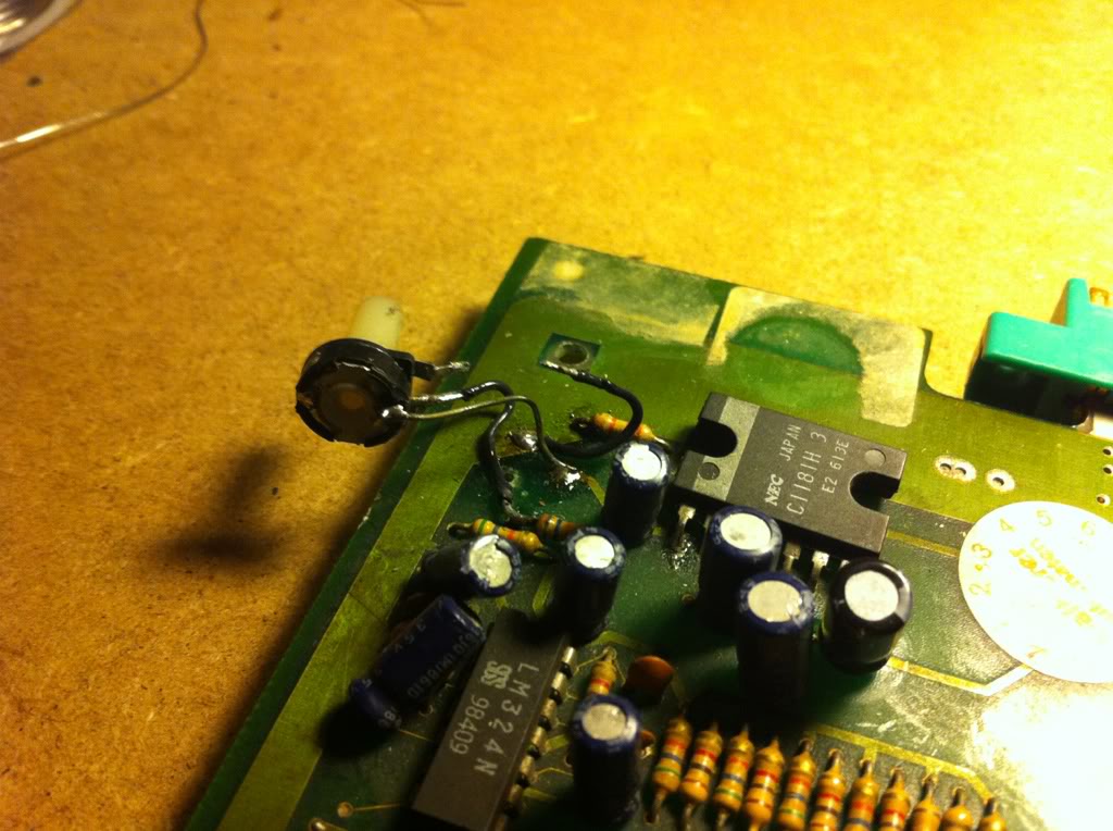
I thought this would be easy. Started off by trying to repair the 2 broken tracks on the pic, but the tracks went under an IC, and I was not able to see where they went. And as they where broken I couldn't just beep at random to find the end points.
Very bold I fired up my brand new Aoyue 474+ desoldering station (a quite good one for the hobbyist I might add) and tried to remove the IC, but I was too impatient and broke it in the process };-( I don't think that I have the 'wiggle' quite right yet...
Well I then found that the track continued under another IC, so fitted a socket and desoldered that too, this time with greater success };-) I now had the 2 end points and was able to patch it with kynar on the solder side and smack in a placement for the broken IC. To my surprise it didn't change a f... thing!
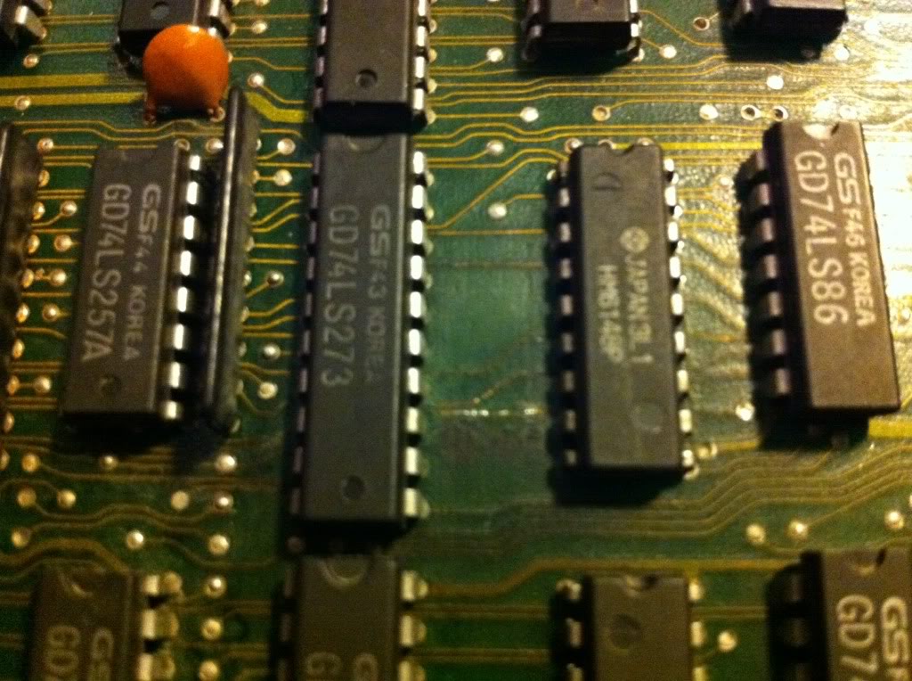
Started shortening adjecent pins on RAMs on the 2nd board, as this usually handles graphics and soon found 2 pieces of HM6148P (4bit wide general purpose RAM some times used for sprites). When shortening some of the data pins on them, the sprites (and also the blue stripes) started acting up.
Decided to desolder both (broke one of them) and test them in the Top2005+. But when trying to find the 6148 in the list of surported SRAMs to test, I couldn't find it. Googled for cross references; they where not there either... };-( the FRAKING thing can only test SRAM that are 8bits wide, WHY!!!
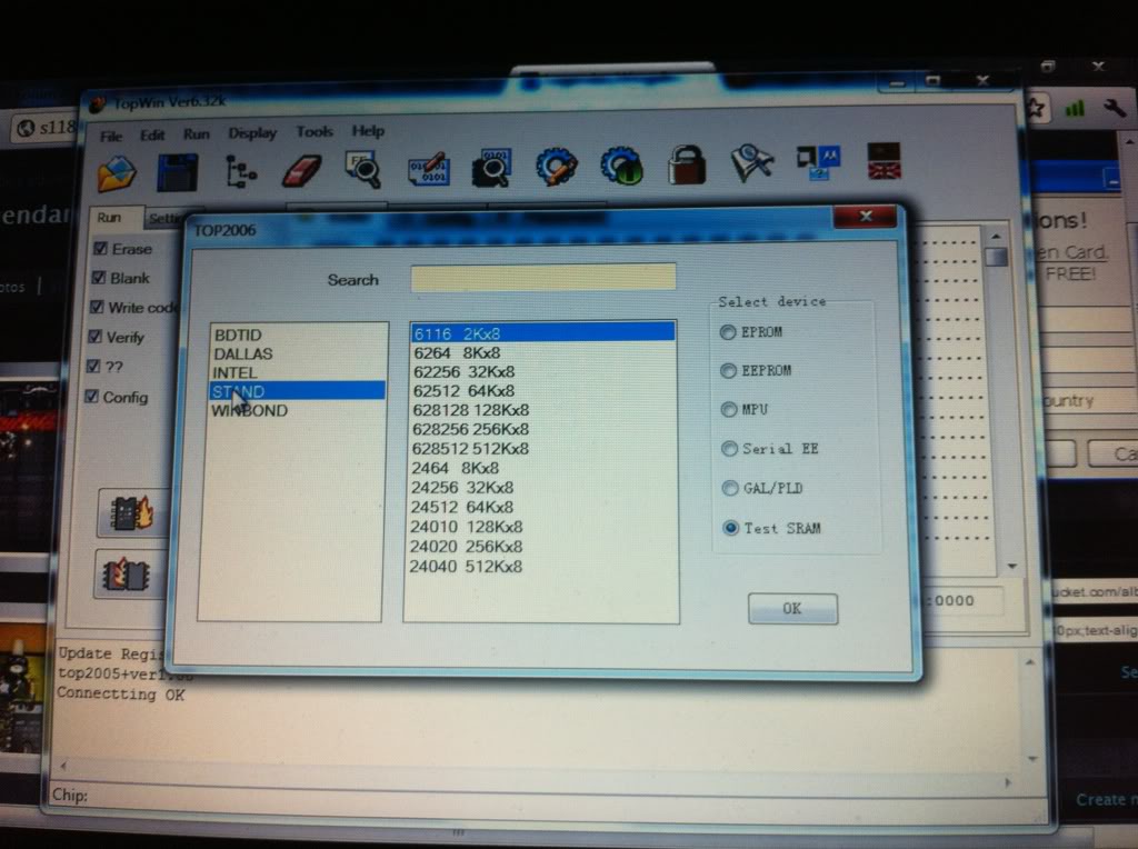
Fitted 2 sockets and reinserted the one chip along with one from a scrap board.
Well now I had a section of the board looking like this.
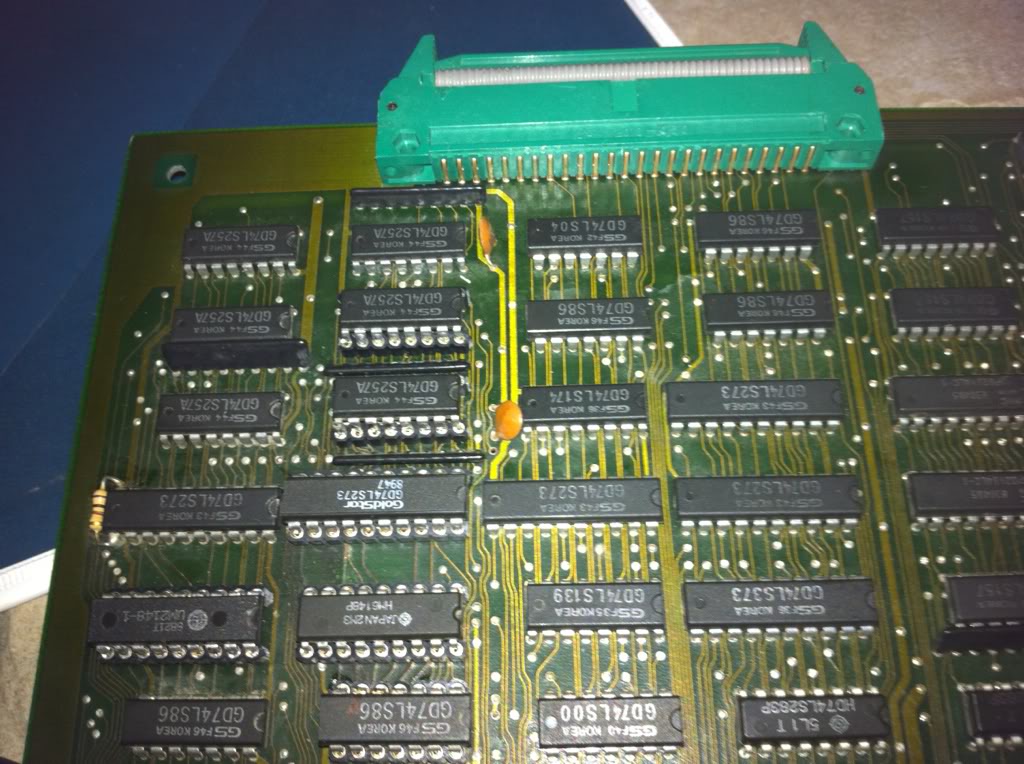
Now poked the data lines of the 2 SRAMs with the scope and found 1 of them stuck high. As I couldn't test the SRAM, I had to assume that it was ok and went looking for what else was on the databus line. Now I was glad that I had socketed some of the ICs, as the track went under some of them. Well first I found the input of a 273 flip-flop; properly here, that the signal is transmitted to the later parts of the graphics system. Then a pull-up resistor array (ahhh, so that's why it's stuck high...it might not be driven at all). It ended at the output of a 257 multiplexer. One of the inputs for that was stuck high (again pull-up resistor), and when closely inspecting the track that went from there to a via using a multimeter, I found it broken. I couldn't see it with the naked eye. Patched it up, and....
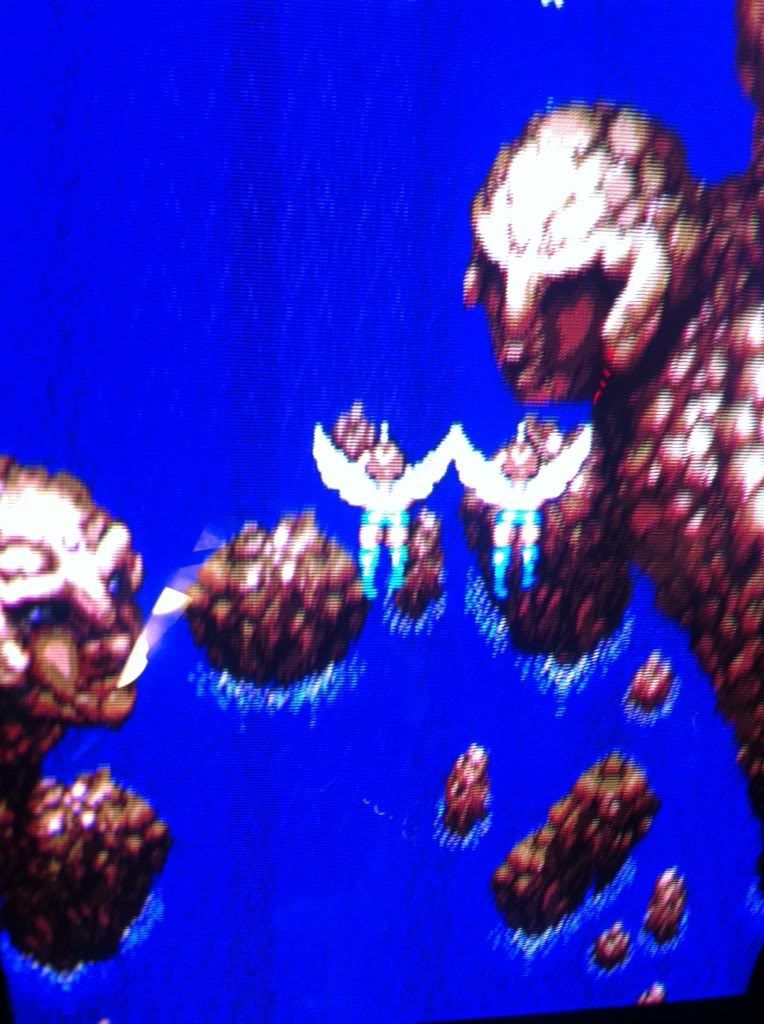
...all sprites back to normal };-D
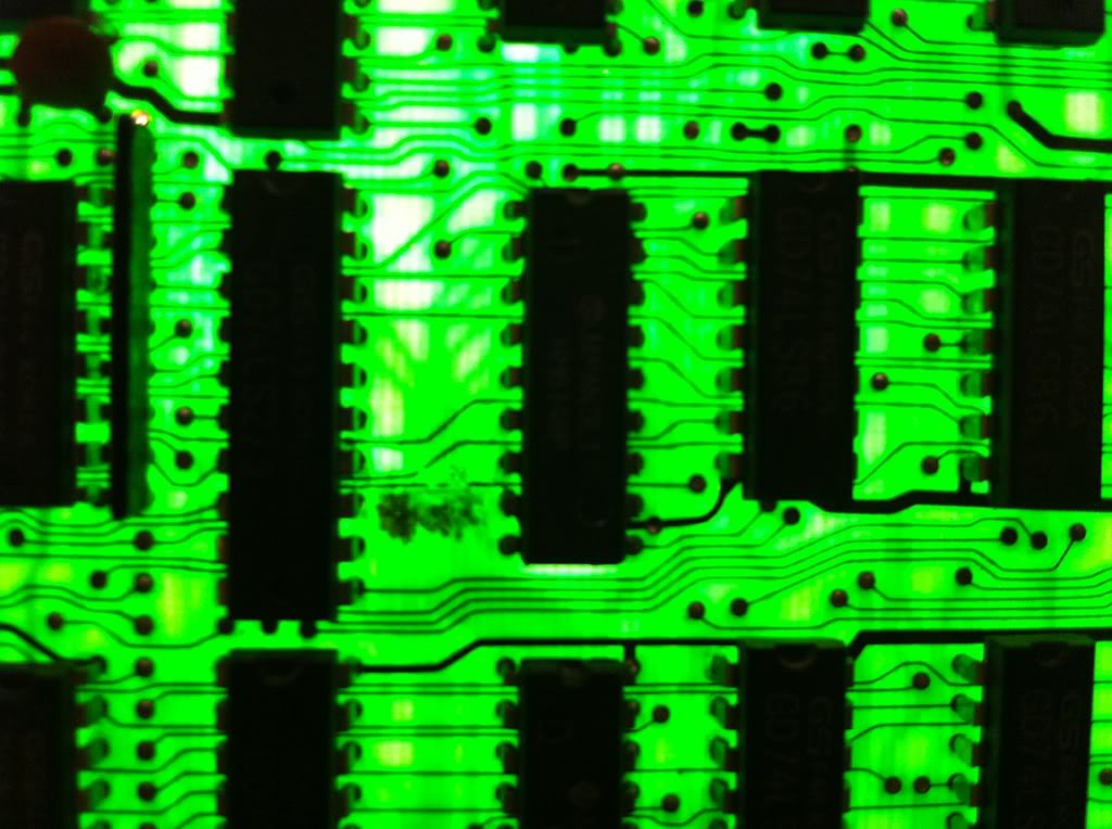
Ended up with a solderside looking like this
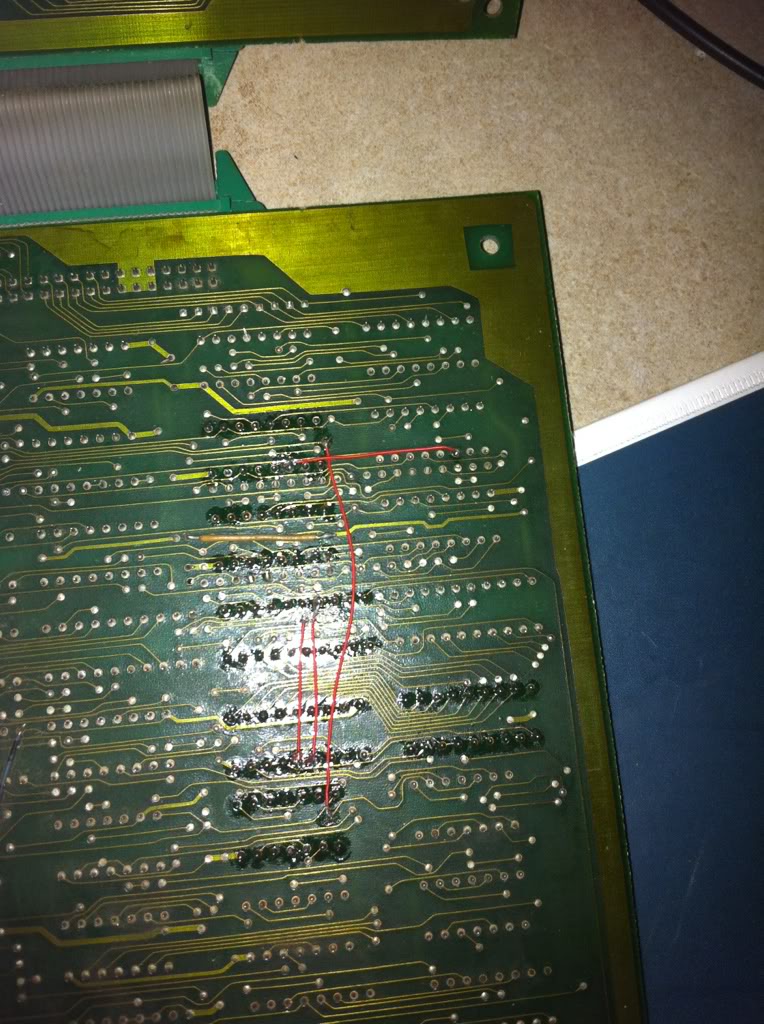
I have a strong feeling, that none of the ICs were bad on this board, I was just unfortunate to break 2 of them during desoldering.
Now the sound pot was fixed in a matter of minutes
and finally I could play a test game.
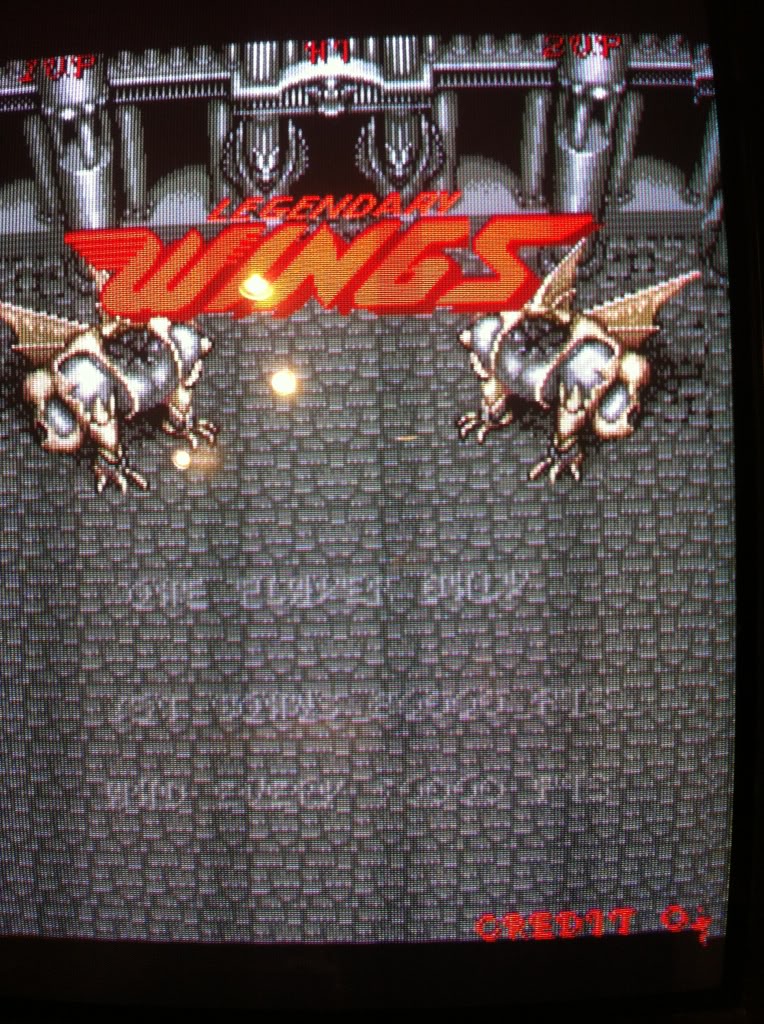
The board do infact still have a small issue; the text when coined up is kind of 'transparent', but as it has no influence on game play, I choose to don't bother for now.
