Arcade Machine Restoration Monitors: Difference between revisions
No edit summary |
No edit summary |
||
| Line 14: | Line 14: | ||
...................................................... | ...................................................... | ||
Anatomy of a CRT Monitor | Anatomy of a CRT Monitor By Dezbaz | ||
In the last few days I found a few TVs with broken necks, So I decided to dissect them and document the results if anyone is interested | In the last few days I found a few TVs with broken necks, So I decided to dissect them and document the results if anyone is interested | ||
Latest revision as of 19:23, 21 February 2013
TV & Monitor Picture Tubes, Power Supplies & Scan Circuits.
RMIT School of Electrotechnology, for Electronics Technicians.
CATHODE RAY TUBES & THEIR ADJUSTMENTS.
Note: I did not write this myself.
If any active member wants a copy of it, send me a PM.
Please add to this if need be. By Dezbaz. VECTOR MONITORS Types of vector monitors as found in Atari's arcade machines. Amplifone Colour, Wells Gardner K6100 Colour. In Sega machines: G08 colour, or cinematronics monitors. In LAI Machines: B&W LAI-KZ-20XYB Chassis, in Atari: B&W G05-801, G05-802, G05-805, 19V2000
......................................................
Anatomy of a CRT Monitor By Dezbaz In the last few days I found a few TVs with broken necks, So I decided to dissect them and document the results if anyone is interested
CRT is Cathode Ray Tube, AKA: Monitor / TV / Screen / Tube
I firstly was trying to understand how it all works myself, and now I see how amazing it is they ever got these to work
So, I got an 8 Pin from a 15" TV. Someone had stolen the yoke for scrap metal, so I kicked the neck off the screen and took it Then I found a 110 degree 25" CRT which was cleanly broken off at the neck, with the yoke intact I would like to do this with a B&W one day, if I ever see one getting trashed
12 Pin, 25", 110 Degree CRT (With an Amplifone Repro Neck board on it)
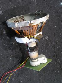
The 3 guns are aimed perfectly through these holes as shown
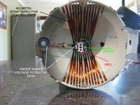
See the convergence strip held on the Yoke (See pic above - Black Writing)
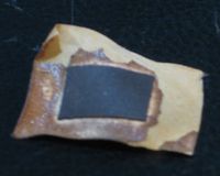
The funny thing about that little strip, how did it get there? Did they remove the yoke, meaning convergence had to be started again? Maybe it was slipped under, which is why it fell off so easy?? We will never know
So knowing the guns are next to one another may help us understand convergence. Since the beams run almost parallel until they reach the centre of the screen, you can see how a convergence strip (a MU Metal strip) can effect certain colors only, when converging. Also you can see how Green is in the centre and harder to control
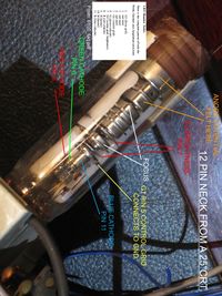
There is a lot going on, so I wanted to know what all the pieces were in the neck of the CRT. This pic shows some of the visible levels as viewed from inside the tube.
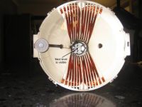
This pic below shows the (insert correct name of the part here) which would press against the glass (On the opposite side as the adode) and cause the HV potential to be felt here and at the metal it's connected to.
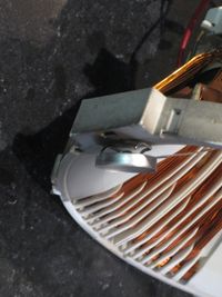
Here are the locations of everything (Heater resistance of this one is 2.2 ohms
