PCB Repair Logs 1942 Bootleg: Difference between revisions
Created page with "==1942 (Bootleg)== <p><table class="infobox vevent" style="width:22em;" cellspacing="5"> <caption class="summary" style=""><b>1942 (Bootleg)</b></caption> <tr class="> <td co..." |
mNo edit summary |
||
| Line 19: | Line 19: | ||
'''Forum Thread:''' [http://www.aussiearcade.com.au/showthread.php/27426-1942-Bootleg-Repair-Log 1942 (Bootleg) PCB Repair]<br> | '''Forum Thread:''' [http://www.aussiearcade.com.au/showthread.php/27426-1942-Bootleg-Repair-Log 1942 (Bootleg) PCB Repair]<br> | ||
<br> | <br> | ||
Sniped this 1942 bootleg board on ebay recently, sold as a faulty, the one guy I outbid was probably annoyed but they saved themselves a right pain in the rear if they were planning on fixing it. | |||
Physically the board didn't look great, there had been quite a bit of repair work done on it, a number of TTL chips were not original, some in sockets, many soldered badly. There were a number of bodgy fixes, wires strung across the board linking things that looked like they would never be connected by the PCB itself. Finally the EPROMs were a mish mash of brands, with mismatching stickers and all looking rather tatty. The silk-screening for the CPU board and the gfx board were different styles, clearly this board pair were not born together. | |||
The initial problem was that its was not JAMMA, nor was it Capcom classic pinout as it has a 22 pin edge connector so it wasn't the standard 1942 bootleg pinout, a quick check with the multimeter showed it also wasn't the 22 pin bootleg pinout. Right at the end of the fix when I was trying to infer the control pin layout did I actually find the 22 pin pinouts that made sense for this board. Initially I had to work it out myself, which actually is quite easy if you have an oscilloscope. The 5V and Ground rails are easy enough to work out as all the TTL chips connect back to this, and for initial troubleshooting of a board you only really need the 5V, the ground, and the video output, enough to power up the board and see what it does. On a running board with no 12V (so the amp is off) the only signals you should see coming out of the board are the 3 colour channels and video sync, the colours look like very weak noisy signals and the sync is a regular pulse. So wiring up the loom was quite easy, except which colour is which. MAME is damn handy to see what a game should look like, it literally was a case of going round with a loose wire touching each of the three outputs to see which made the sea blue during attract mode, the other two were a 50/50 guess and suddenly I had a full video output. | |||
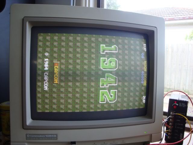
The game was running so I thought I was half way there, sadly planes were buzzing around happily over a pure blue sea, no sea surface graphics, no islands and no aircraft carrier - the background was totally missing. The player sprite was also a bit flickery from time to time, with lines of flickeryness extending out behind it. | |||
<br> | |||
<br> | |||
[[File:Pcb repair 1942 bootleg 1.jpg]] | |||
<br> | |||
<br> | |||
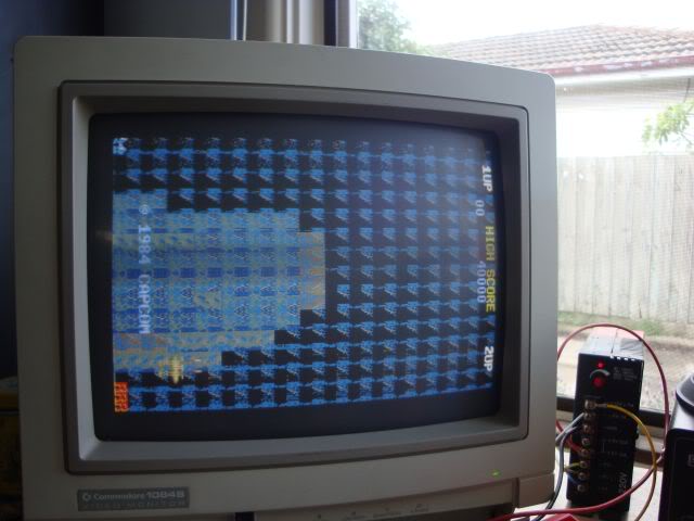
Every once in a while I would get bursts of graphics scrolling past as backdrop but they were blocky and just wrong. | |||
<br> | |||
<br> | |||
[[File:Pcb repair 1942 bootleg 2.jpg]] | |||
<br> | |||
<br> | |||
The title screen was also wrong, it should be a black background, but I had blue, sometimes blank and sometimes with crap all over it. | |||
<br> | |||
<br> | |||
[[File:Pcb repair 1942 bootleg 3.jpg]] | |||
<br> | |||
<br> | |||
Initially I thought this was a video ram problem for the area dealing with the back plane, it was no consistent so RAM was the logical suspect. The RAM was easy to find as when interrupting the output pins I got single pixel lines scrolling past as the back drop, it was a standard 6116 SRAM chip, which tested fine when removed. Strung out above the SRAM chip were 3 27c128 eproms, one in its original socket, 2 in replaced sockets with a wire soldered across them to fix a mangled track. Hitting these with a scope showed that they were all outputting a healthyish signal and were addressed by generally healthy looking address lines. The 6116 chip was enabled and everything looked fine. The data bus was controlled by a 74LS377 that I removed for testing and sadly it passed all tests. | |||
<br> | |||
<br> | |||
[[File:Pcb repair 1942 bootleg 4.jpg]]<br><br> | |||
At this point I finally got round to dumping the ROM contents, none of the 3 ROMs by the 6116 were recognised, the main program EPROM (a 27c64) was not even seen by my tester, yet when it was told to blindly drive the chip gave a dump that was an exact match for the 1st ROM in the Capcom set. On the far side of the GFX board were 5 other 27c128 ROMS, 3 dumped fine and matched the capcom set, one had contents not recognised and one was totally dead - not detected and gave a dump full of FFs. The 3 chips that read fine still had their original stickers on them and were all Mistubishi chips, the remaining two had no stickers and were a TI and a Hitachi ROM - not original. | |||
Looking in the MAME set and working out what the locations meant (another trouble with bootleg boards is often the chip location info is missing from the silk-screening) it was odd that only 4 of the chips should be 27c128s, one should be a 27c64, the 4th one down. EPROMs in a stack often share the same address bus, ie A0 goes to the same pin on all chips, as do all the A lines. The 4th socket had no connection to pin 1, totally correct for a 27c64 but wrong for the 27c128 EPROM that was in it. By reading the ROM contents out and diffing them in blocks to the MAME set it seems someone, for some odd reason had taken the time to consolidate the ROM contents even though the board wouldn't support it. The 128kbit EPROM in the 4th socket (which was wired to address only a 64kbit chip) contained the correct 64kbit code for that board location in its lower 64kb section, and the 1st 64kbit of the 128kb EPROM that should live in the 5th socket. The 5th EPROM was totally dead so I couldn't see what the loon who had done this had done there. It amazes me that someone has the understanding to do perform this strange act without also having the knowledge to know why it makes no sense with this board. Anyway - I erased the 27c128 from socket 4, burnt the code for chip 5 and moved it down one socket. Grabbed a 27c64 from my stash and burnt the correct contents for socket 4, flicked the power and found no bloody change whatsoever. Mildly annoying but not hugely surprising, these EPROM contain the sprite data and over half the data was correct when I got it, potentially later levels would have had mashed sprites but attract mode was the same old same old fault. | |||
Back to the backdrop ROMs, the MAME set contains 6x 64kbit ROMs for this location on the board, but I had 3x128 kbit EPROMs, same total capacity by fewer chips. Was not surprised when the 1st chip was found to contain the data from the 1st pair of 64kbit chips from the MAME set back to back, the other 2 eproms contained mostly the same data but there were differences widespread through the data sets. Its possible that as this is a bootleg board the ROMs will be different, but as this is gfx data its less likely to have been redesigned. The second chip also had a large blank gap in the middle of it and I was wondering if the backdrop data was supposed to be where the hole was. So I took backup dumps of the 2 EPROMs, erased them, made back to back data sets from the MAME set in a hex editor and burnt the new data to the chips. Again this made not one bit of difference. | |||
So I decided to run the board without the 74LS377 chip and got a surprising effect, the colours of the backdrop came good despite the graphics being missing, or rather a single tile due to the fact the bus was floating. | |||
<br><br> | |||
[[File:Pcb repair 1942 bootleg 5.jpg]]<br><br> | |||
The battleship outline appeared, and despite the display flicking from dark gfx to bright gfx every once in a while.. | |||
<br><br> | |||
[[File:Pcb repair 1942 bootleg 6.jpg]]<br><br> | |||
...the islands and the sea colouring was correct. | |||
<br><br> | |||
[[File:Pcb repair 1942 bootleg 7.jpg]]<br><br> | |||
This suggested that the system was working properly but it wasn't being told to display the backdrop, also when the 377 was back on the board interrupting the EPROMs seemed to "load" some crap into the system which would then scroll down the screen a second later. Trouble was the LS377 tested fine again and dropping in a spare didn't fix the problem. | |||
At this point I ended up going off on a trip through the logic trying to find where things went, sadly what I took as being suspicious turned out to be totally normal, so my 3 evening voyage was a bit pointless. Basically I was trying to find a non existent fault that was causing the normal operation of a clock pin to a pair of 74LS174s. For some reason on the 3rd evening the board decided to taunt me. At the same time the colours went nuts and the backdrop graphics appeared for about 30 seconds, long enough for me to hit my suspect chips with a scope and find that nothing much had changed from when the background was missing to when it was scrolling merrily along. Probably the biggest waste of time was tracing a track on the CPU board up to the edge connector, through to the gfx board edge connector and then losing it. None of the tracks coming out from the edge connector were connected to it, the track was on the parts side of the PCB so I couldn't eyeball it either as it was under the connector. I ended up removing the 50 way connector only to find the track really didn't go anywhere, it was just a pad, another joy of bootleg boards is that they often have errors or were not designed from scratch for the game they ended up running. | |||
Anyway, out of desperation I went around looking at all the chips on the boards, everything looked fine, eventually I found a 74LS374 chip that looked very slightly odd on the scope. If it was interrupted its outputs would crap out totally but when not interrupted they were a bit weaker than I would consider normal. So I desoldered it, found it tested OK but decided to fit a new chip. This also changed nothing but when I then went back over the nearby chips I clearly disturbed something, as soon as I hit one of the pins on an LS273 chip the backdrop flicked up on the screen. This is very suspicious, I would suspect that 273 except I had not been over it a dozen times or more with the probe before hand, its outputs look very good on the scope and the fault is consistently gone. Its been 2 days now with many many reboots of the board and not once has the backdrop failed. | |||
The only odd issue was that the middle of the islands was a mess, as was the aircraft carrier and sometimes blocks of crap would pop up in the sea. | |||
<br><br> | |||
[[File:Pcb repair 1942 bootleg 8.jpg]]<br> | |||
<br> | |||
[[File:Pcb repair 1942 bootleg 9.jpg]]<br><br> | |||
One thing I had undone was a bodgy solder joint joining a track to the 5V rail, the laquer had been scratched off and a big drop of solder used to bridge the gap. I had removed this earlier in my attempts to narrow down the issue as I suspected it was left over from previous troubleshooting but I decided to put it back, this fixed the aircraft carrier and the islands!! | |||
The odd block of rubbish and sprite flicker was still popping up from time to time, thoroughly bored of scoping round the board I wondered if the problem was due to the fact that there was not a single capacitor on the board outside of the amp section, or the one that held the reset line until the board had powered up fully. Usually you see caps across the 5V and 0V to act as reservoir capacitors to smooth out any sags in the voltage. So I fitted a couple and the glitchyness of the player sprite vanished. | |||
<br><br> | |||
[[File:Pcb repair 1942 bootleg 10.jpg]]<br><br> | |||
[[File:Pcb repair 1942 bootleg 11.jpg]]<br><br> | |||
[[File:Pcb repair 1942 bootleg 12.jpg]]<br><br> | |||
All that was left was to wire up the amps 12V feed and thankfully the sound was fine, after fitting the 1P control links to the loom the game plays perfectly, or it would had the PSU in my Vertical Cab not decided that today was the day to die - ho hum. It works in my horizontal cab but its not easy to play standing sideways. | |||
When the sun finally comes out I am going to give this board a damn good wash, probably in piping hot holy water, its pretty mucky, then it can dry outside. | |||
<br>[[PCB_Repair_Index|Back to PCB Repair Index]] | <br>[[PCB_Repair_Index|Back to PCB Repair Index]] | ||
Revision as of 10:43, 22 August 2012
1942 (Bootleg)
 |
|
| PCB Image | Reserved |
|---|---|
| Pin Out | Reserved |
Repairer: Womble
Forum Thread: 1942 (Bootleg) PCB Repair
Sniped this 1942 bootleg board on ebay recently, sold as a faulty, the one guy I outbid was probably annoyed but they saved themselves a right pain in the rear if they were planning on fixing it.
Physically the board didn't look great, there had been quite a bit of repair work done on it, a number of TTL chips were not original, some in sockets, many soldered badly. There were a number of bodgy fixes, wires strung across the board linking things that looked like they would never be connected by the PCB itself. Finally the EPROMs were a mish mash of brands, with mismatching stickers and all looking rather tatty. The silk-screening for the CPU board and the gfx board were different styles, clearly this board pair were not born together.
The initial problem was that its was not JAMMA, nor was it Capcom classic pinout as it has a 22 pin edge connector so it wasn't the standard 1942 bootleg pinout, a quick check with the multimeter showed it also wasn't the 22 pin bootleg pinout. Right at the end of the fix when I was trying to infer the control pin layout did I actually find the 22 pin pinouts that made sense for this board. Initially I had to work it out myself, which actually is quite easy if you have an oscilloscope. The 5V and Ground rails are easy enough to work out as all the TTL chips connect back to this, and for initial troubleshooting of a board you only really need the 5V, the ground, and the video output, enough to power up the board and see what it does. On a running board with no 12V (so the amp is off) the only signals you should see coming out of the board are the 3 colour channels and video sync, the colours look like very weak noisy signals and the sync is a regular pulse. So wiring up the loom was quite easy, except which colour is which. MAME is damn handy to see what a game should look like, it literally was a case of going round with a loose wire touching each of the three outputs to see which made the sea blue during attract mode, the other two were a 50/50 guess and suddenly I had a full video output.
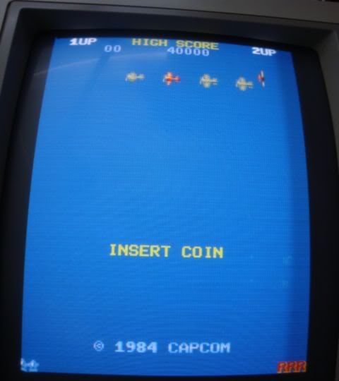
The game was running so I thought I was half way there, sadly planes were buzzing around happily over a pure blue sea, no sea surface graphics, no islands and no aircraft carrier - the background was totally missing. The player sprite was also a bit flickery from time to time, with lines of flickeryness extending out behind it.
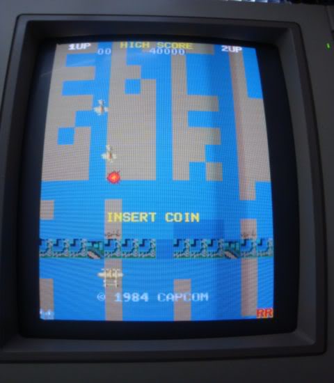
Every once in a while I would get bursts of graphics scrolling past as backdrop but they were blocky and just wrong.
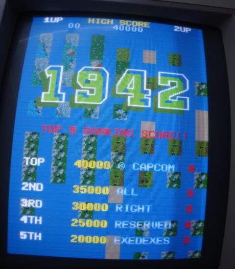
The title screen was also wrong, it should be a black background, but I had blue, sometimes blank and sometimes with crap all over it.
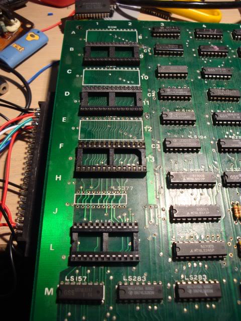
Initially I thought this was a video ram problem for the area dealing with the back plane, it was no consistent so RAM was the logical suspect. The RAM was easy to find as when interrupting the output pins I got single pixel lines scrolling past as the back drop, it was a standard 6116 SRAM chip, which tested fine when removed. Strung out above the SRAM chip were 3 27c128 eproms, one in its original socket, 2 in replaced sockets with a wire soldered across them to fix a mangled track. Hitting these with a scope showed that they were all outputting a healthyish signal and were addressed by generally healthy looking address lines. The 6116 chip was enabled and everything looked fine. The data bus was controlled by a 74LS377 that I removed for testing and sadly it passed all tests.
At this point I finally got round to dumping the ROM contents, none of the 3 ROMs by the 6116 were recognised, the main program EPROM (a 27c64) was not even seen by my tester, yet when it was told to blindly drive the chip gave a dump that was an exact match for the 1st ROM in the Capcom set. On the far side of the GFX board were 5 other 27c128 ROMS, 3 dumped fine and matched the capcom set, one had contents not recognised and one was totally dead - not detected and gave a dump full of FFs. The 3 chips that read fine still had their original stickers on them and were all Mistubishi chips, the remaining two had no stickers and were a TI and a Hitachi ROM - not original.
Looking in the MAME set and working out what the locations meant (another trouble with bootleg boards is often the chip location info is missing from the silk-screening) it was odd that only 4 of the chips should be 27c128s, one should be a 27c64, the 4th one down. EPROMs in a stack often share the same address bus, ie A0 goes to the same pin on all chips, as do all the A lines. The 4th socket had no connection to pin 1, totally correct for a 27c64 but wrong for the 27c128 EPROM that was in it. By reading the ROM contents out and diffing them in blocks to the MAME set it seems someone, for some odd reason had taken the time to consolidate the ROM contents even though the board wouldn't support it. The 128kbit EPROM in the 4th socket (which was wired to address only a 64kbit chip) contained the correct 64kbit code for that board location in its lower 64kb section, and the 1st 64kbit of the 128kb EPROM that should live in the 5th socket. The 5th EPROM was totally dead so I couldn't see what the loon who had done this had done there. It amazes me that someone has the understanding to do perform this strange act without also having the knowledge to know why it makes no sense with this board. Anyway - I erased the 27c128 from socket 4, burnt the code for chip 5 and moved it down one socket. Grabbed a 27c64 from my stash and burnt the correct contents for socket 4, flicked the power and found no bloody change whatsoever. Mildly annoying but not hugely surprising, these EPROM contain the sprite data and over half the data was correct when I got it, potentially later levels would have had mashed sprites but attract mode was the same old same old fault.
Back to the backdrop ROMs, the MAME set contains 6x 64kbit ROMs for this location on the board, but I had 3x128 kbit EPROMs, same total capacity by fewer chips. Was not surprised when the 1st chip was found to contain the data from the 1st pair of 64kbit chips from the MAME set back to back, the other 2 eproms contained mostly the same data but there were differences widespread through the data sets. Its possible that as this is a bootleg board the ROMs will be different, but as this is gfx data its less likely to have been redesigned. The second chip also had a large blank gap in the middle of it and I was wondering if the backdrop data was supposed to be where the hole was. So I took backup dumps of the 2 EPROMs, erased them, made back to back data sets from the MAME set in a hex editor and burnt the new data to the chips. Again this made not one bit of difference.
So I decided to run the board without the 74LS377 chip and got a surprising effect, the colours of the backdrop came good despite the graphics being missing, or rather a single tile due to the fact the bus was floating.
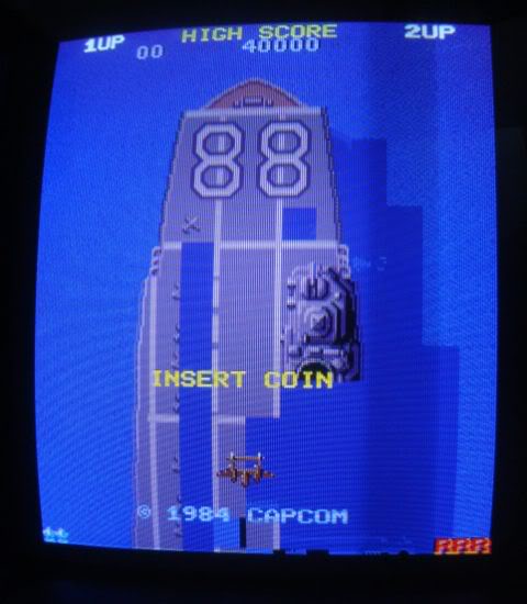
The battleship outline appeared, and despite the display flicking from dark gfx to bright gfx every once in a while..
...the islands and the sea colouring was correct.
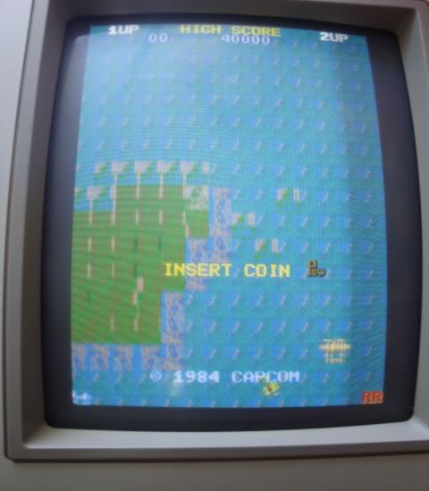
This suggested that the system was working properly but it wasn't being told to display the backdrop, also when the 377 was back on the board interrupting the EPROMs seemed to "load" some crap into the system which would then scroll down the screen a second later. Trouble was the LS377 tested fine again and dropping in a spare didn't fix the problem.
At this point I ended up going off on a trip through the logic trying to find where things went, sadly what I took as being suspicious turned out to be totally normal, so my 3 evening voyage was a bit pointless. Basically I was trying to find a non existent fault that was causing the normal operation of a clock pin to a pair of 74LS174s. For some reason on the 3rd evening the board decided to taunt me. At the same time the colours went nuts and the backdrop graphics appeared for about 30 seconds, long enough for me to hit my suspect chips with a scope and find that nothing much had changed from when the background was missing to when it was scrolling merrily along. Probably the biggest waste of time was tracing a track on the CPU board up to the edge connector, through to the gfx board edge connector and then losing it. None of the tracks coming out from the edge connector were connected to it, the track was on the parts side of the PCB so I couldn't eyeball it either as it was under the connector. I ended up removing the 50 way connector only to find the track really didn't go anywhere, it was just a pad, another joy of bootleg boards is that they often have errors or were not designed from scratch for the game they ended up running.
Anyway, out of desperation I went around looking at all the chips on the boards, everything looked fine, eventually I found a 74LS374 chip that looked very slightly odd on the scope. If it was interrupted its outputs would crap out totally but when not interrupted they were a bit weaker than I would consider normal. So I desoldered it, found it tested OK but decided to fit a new chip. This also changed nothing but when I then went back over the nearby chips I clearly disturbed something, as soon as I hit one of the pins on an LS273 chip the backdrop flicked up on the screen. This is very suspicious, I would suspect that 273 except I had not been over it a dozen times or more with the probe before hand, its outputs look very good on the scope and the fault is consistently gone. Its been 2 days now with many many reboots of the board and not once has the backdrop failed.
The only odd issue was that the middle of the islands was a mess, as was the aircraft carrier and sometimes blocks of crap would pop up in the sea.
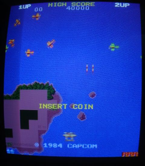
One thing I had undone was a bodgy solder joint joining a track to the 5V rail, the laquer had been scratched off and a big drop of solder used to bridge the gap. I had removed this earlier in my attempts to narrow down the issue as I suspected it was left over from previous troubleshooting but I decided to put it back, this fixed the aircraft carrier and the islands!!
The odd block of rubbish and sprite flicker was still popping up from time to time, thoroughly bored of scoping round the board I wondered if the problem was due to the fact that there was not a single capacitor on the board outside of the amp section, or the one that held the reset line until the board had powered up fully. Usually you see caps across the 5V and 0V to act as reservoir capacitors to smooth out any sags in the voltage. So I fitted a couple and the glitchyness of the player sprite vanished.
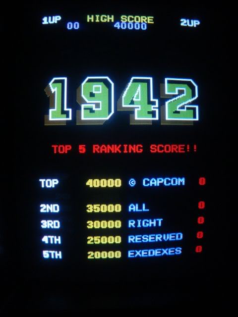
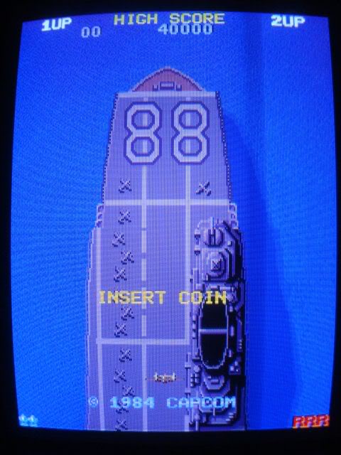
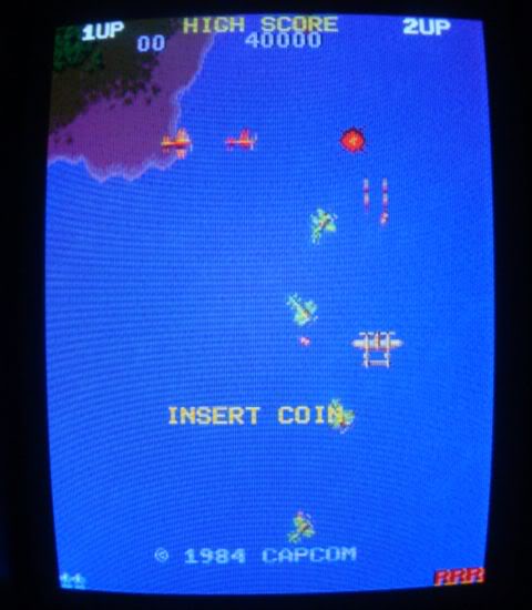
All that was left was to wire up the amps 12V feed and thankfully the sound was fine, after fitting the 1P control links to the loom the game plays perfectly, or it would had the PSU in my Vertical Cab not decided that today was the day to die - ho hum. It works in my horizontal cab but its not easy to play standing sideways.
When the sun finally comes out I am going to give this board a damn good wash, probably in piping hot holy water, its pretty mucky, then it can dry outside.