PCB Repair Logs Galaxian: Difference between revisions
mNo edit summary |
mNo edit summary |
||
| Line 14: | Line 14: | ||
</tr> | </tr> | ||
</table></p> | </table></p> | ||
<br> | <br> | ||
<br> | <br> | ||
| Line 21: | Line 19: | ||
<br> | <br> | ||
<br> | <br> | ||
'''Repairer:''' [http://www.aussiearcade.com.au/member.php/1-Arcade-King Arcade King]<br> | |||
'''Forum Thread:''' [http://www.aussiearcade.com.au/showthread.php/541-Galaxians-and-Xevios Galaxian PCB Repair]<br> | |||
<br> | |||
<br> | |||
=== Original Midway Galaxians cheers Geoff. === | === Original Midway Galaxians cheers Geoff. === | ||
Revision as of 13:09, 5 February 2013
Galaxian
 |
|
| PCB Image | Midway Galaxian |
|---|---|
| Pin Out | Reserved |
Repairer: Arcade King
Forum Thread: Galaxian PCB Repair
Original Midway Galaxians cheers Geoff.
Bad 74ls138@8m
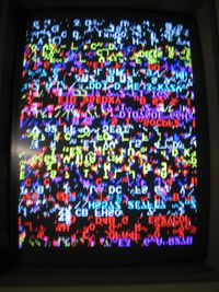
74ls194@2k Now I get a screen full of graphics flashing
2114 ram@3F now instead of getting a screen full of G's i get flashing BAD RAM A. The R in Ram is messed up.
Bad 74ls74@2d and 3d. Starfield is now back
Found a lot of bad sockets on this board so I've gone through and replaced them all. Just found a socketed 74ls393 many of the pins not making contact.
Bad 74ls175@6R output pin 2 stuck low.
Bad 74ls20 @3P pin 4 a input was low pulling down a output of a 74ls377 pin 19
Bad 74ls10@5D output was pulling the circuit low effecting the 74ls02@3P pin 6 and the 74ls377 @ 6P pin 1
Bad 74ls10@ 4P. Output pin 6 dead.
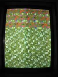
Background is now black as it should be and colour look good. The starfield is working normally in the background however there is nothing but garbage on the screen.
Turns out the wiring on my single rom hack was a tad dodgy. Now the game goes through the first part of the test screen with all the letters and number scrolling sideways then resets as it goes to the nest part of the test.
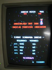
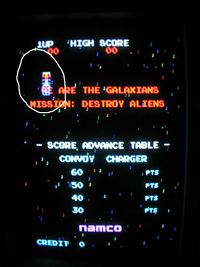
Found a 74ls367@8D bad output pulling a address line down. Didnt fix the resetting problem but after many hours of going over everything I finally found a dead input on pin 12 of a 74ls367 @ 8D. This lead me to a 74ls259 @ 9N outputs were dead as a door nail. Replacing the chip booted up the board. Seems to look great but aliens are stuck up the top and in the intro screen the are split half, inverted and stuck at top, also in the demo when the aliens dive they split apart then join back together.
Bad 74ls163 @ 5T was the cause of the diving aliens being stuck at the top but they are still spit in two and inverted.
Bad socket on the 74ls245@5J one of the characters was not showing up complete.
Found the split character problem was a 74ls157 @ 6J.
I found a 74ls86 with a dead input pin 10 which leads to the 157 pin 13. There was a broken trace to pin 13 I fixed it but line still dead. Replaced the 157 and characters are fine, pin 13 of the 157 is a input also so I need to do some more digging. The trace to this pin was cut I couldn't even see it until I ran some solder over it to repair it. In this case I used a socket when replacing the chip because the solder holes didnt look real healthy, I've actually found a few like this on this poor old board.
I can see on MAME the aliens at the title screen are upside down but in game they are perfect. This line must flip them for the title screen.
Ok pin 13 on the 157 and pin 10 on the 86 trace back to a 74ls273 @ 4L pin 19. Pin 19 (output) was pulsing but somewhere the line is broken. I decided to cut the chip off to see whats underneath, Its also fair to note this chip and the 157 had been replaced by some one else in the past.
I cut the chip off desolded all the pins and with my trusty old desoldering pump cleaned the holes up. The problem wasn't the hole itself but at the end of the trace. I cleaned it up ran some solder over it and found another small cut WTF?
Popped a new socket in replaced the chip fixed the trace fired her up now she's perfect! I have no idea why the lines were cut, it certainly wasnt due to the age of the board, she's in pretty damn good nick for something made 27 years ago!
Now I have the graphics worked out its time to finnish my harness and get the control and sound hooked up.
Sound
The LM777 amp was getting super hot so bad you would burn your fingers on it until finally it died(didnt take long.
I had no replacement chips for this so I decided to make my own amp out of common parts IE: a Fairchild MB3730. Playing around for ages I found pin 2 is the output, pin 6 is the input and pin 16 is +12v. I'll go into details of the home made "bodgy amp" after.
OK started her up with LOTs of background static and noise. Sounds that can be heard.
Coin insert Alien explosion.
Seem to be missing heaps, I instantly suspected a 74ls259 @ 9L which like all these damn EL SALVADOR chips were corroded to buggery.
This chip(from the troble shooting guide) effects tone generation, explosion and wrong tones in other sounds. Replaced the chip and what do you know the static background noise and hums were gone. Started the game up and I had the in game background noise, explosion when your ship dies and the alien diving noise back, still seems im missing the sound when you shoot.
Turned out to be a simple problem. Legs broken on a 0.1k100T green cap. The trouble shooting guide helped heaps with this problem.
I also replaced the Lm234 just for the hell of it, the legs were badly corroded.
Board is now 100% working and fixed just need to tidy up my home made amp into something that looks presentable .
Home Made amp for Galaxians
What you need.
- Fairchild MB3730
- Wire
- 220uf 16V or higher volt cap
- 22uf 16v or higher volt cap
- 4.7uf 16v cap
- a couple of 154K green caps
First cut off the uneeded resistors and caps from the old amp @ C50, R95, R94, C48, R93, C47, R92, C51, C49, C46. Solder the 4.7uf cap at position C46 with positive facing the volume pot.
Going from left to right on the amp pins 1 through to 7, connect pin 7 to pin 16 where the old lm377 was +12 V.
Connect pin 6(MB3730) to pin 2(lm377) output 1
Connect pin 5(MB3770) to pin 15(lm377) output 2
Connect pin 4 to the nearest Ground
For the caps im going to use positions R94 and C48 to make everything neat, Ive used C48 for the 22uf cap and R94 for the 220 uf cap. The Positive side of the cap will be towards the end of the board. Ok now you have to ground the neg side of the caps. The trace below the board convienetly joins the two caps so all we have to do is find the nearest ground and run a wire to it.
Connect pin 3(MB3730) to pin 8(lm377), this links to the 220uf cap Connect pin 2(MB3730) to pin 9(lm377), this links to the 22uf cap Pin 1(MB3730) goes to pin 7(lm377) this is the input.
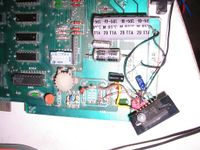
Run a green cap on each output line to ground you can see from my pic what i did. I stole the caps off a Tumble Pop board
Your new amp is ready to go fire her up and if you get no smoke then you did good . I drilled a few holes in the pcb to mount the amp.
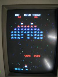
Just did the fourplay 4 in 1 hack which includes Galaxians, Super Galaxians, Galaxians X and Exodus and I must say SWEEET! Galaxians X is rather fun! See pics for the board with completed hack.
