PCB Repair Logs Midnight Resistance
Midnight Resistance
 |
|
| PCB Image | Midnight Resistance |
|---|---|
| Pin Out | Reserved |
Repairer: Womble
Forum Thread: Midnight Resistance PCB Repair
Board 1
Bought a Midnight Resistance board recently, was up with a buy-it-now very cheap so I grabbed it, I love the game, its the reason my cab has rotary sticks installed.
Anyway the seller said it worked fine except there was no sound, well not quite, when powered up it was clear that the video was missing the blue signal,
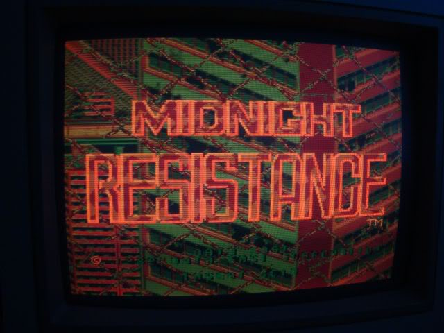

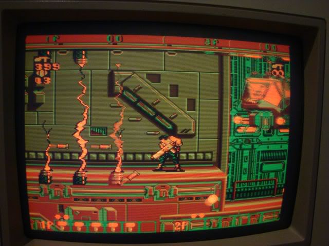
Originally thought it was my test bench jamma loom playing up as its getting very unreliable but poking the scope at the jamma edge connector showed that green and red were happily buzzing away but blue was silent. I visually followed the track back to NB1 (one of three - the other two pass the red and green) and then used the continuity meter to buzz around the nearby chips, pin 7 of a 74LS174 which was silent on the scope.
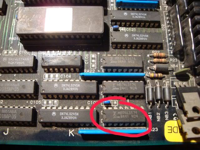
It was a Fujitsu chip, and these are often known to die by losing internal connectivity to a pin. The simple test is to piggy back a known good chip on top of the original. If it has died by losing a pin the piggy backed chip will light up that leg, and in this case the graphics were instantly fixed.
You can see the piggy backed chip circled in red.
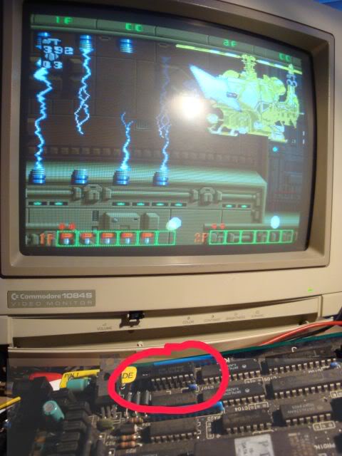
Piggy backing is not a guaranteed test tho, in fact in some circumstances it can result in the piggy backed chip being destroyed, but for F branded chips with missing outputs its always worth a go. In fact my piggy backer chips tend to be F brand chips I have suspected as faulty and de-soldered only to find that they are ok, will never put an F back on a board as they are so flaky, they make for good piggy backers though as I don't mind if they get zapped.
Anyway - I left piggy backed chip on and moved to the sound issue only to find that the speakers would sometimes crackle and sometimes not, I also got a lot of issues with the gfx as I was moving the board around, the red channel would flicker and the screen would lose sync. Turns out the JAMMA connector needed a good polish, it didn't look too crusty but a rub with brasso removed all the instability issues. The speaker hiss was then constant and the volume pot crancked it up and down so the amp section was also fine. I did a quick ESR check on the electrolytics but they were all good. When I powered it back up again I got the gunshot sound when coining the board up. Its possible that the sound issue was just a badly oxidised jamma connector but it seemed unlikely. I could get the coin up noises, and the "erk" noises as the enemies were hit, but no music or other effects, eventually the sounds stopped totally and I could never get them back for more than a second or so after that. In fact when the dipswitch was set to attract sounds on the board emitted a long tone until powered off, it never made another noise so I assumed the sound section was crashing long before I could coin it up. When attract mode sounds were off the 1st time it tried to do anything was on coin-up so that would explain why I could get a burst of sound out of it.
As the sound CPU on these boards is a surface mount chip I started off looking at the easier option of the TMM2063 - the sound RAM for the audio CPU, the address line inputs looked nice and clean but the outputs were a real mess...
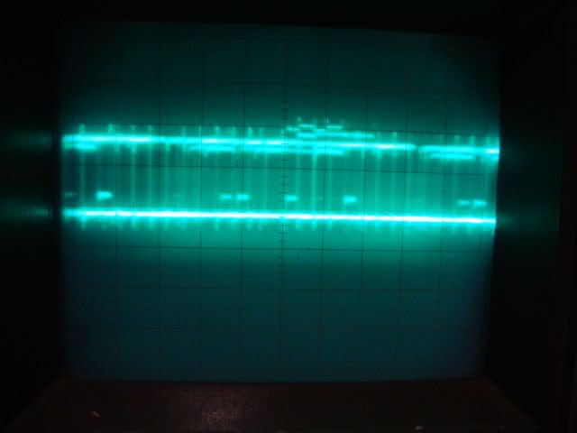
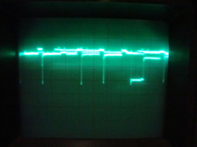
...signal voltage very unstable, no clear distinction between logic high and logic low. Usefully enough there were other TMM2063s on the board that were involved with the game execution itself so I could poke the scope at the outputs of those chips, clearly they were ok as the game was running. The outputs of the others looked nice and clean...
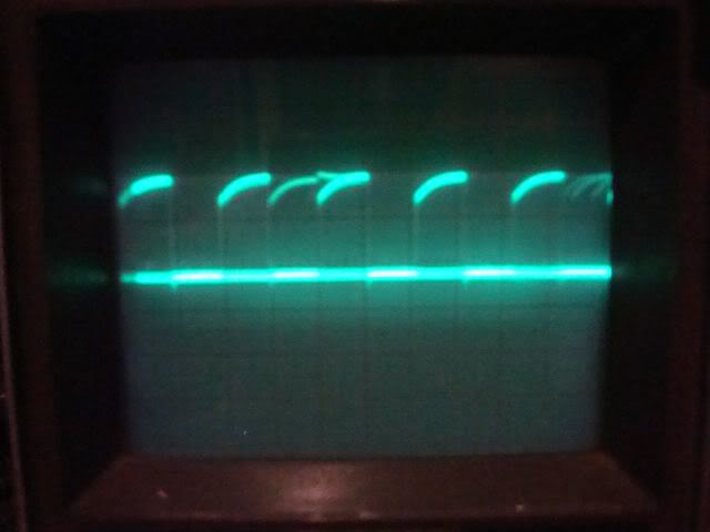
...so the chief candidate was indeed the sound SRAM.
Fired up the de-solder station and whipped out the 74LS174 and the TMM2063.
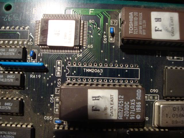
The TMM2063 failed the read write test on my eprom reader so I dug out a scrap board and de-soldered a Sony CXK5864BSP-10L chip which is a pin for pin compatible chip. How do I know this? The first thing to do when trying to find a replacement is to find a RAM chip that has the same number of pins as the one you are trying to replace, then google for the data sheet and compare the description. Both chips were described as "65536 bit CMOS SRAM organised as 8,192 words by 8 bits", then double check the chip pin outs are the same. Ignoring the fact that some manufacturers label their data pins as D0-D7 and some as D1-D8, and the same for the A pins you usually find they are totally compatible, the only other concern is the speed of the chip, which is denoted by the last number of the chip name eg CXK5864BSP-10L is a 100nSec chip, -70 would be a 70 nSec, -60 as 60nSec etc etc. If you don't have a collection of scrap boards then it gets a bit harder as you have to find a vendor then google what they are selling, you can't start with the simple eyeball conclusion that if it doesn't have the same number of pins it can be compatible.
I also de-soldered a Hitachi (i.e. bulletproof) 74LS174 chip and soldered it into the board, I tend to fit machined pin sockets for RAM chips if I can, firstly to save the SRAM chip from another blast of heat and secondly to future proof the board. The logic chip will probably last another 20 years, the SRAM chip is far less likely to so sockets save the PCB from another de soldering and make the board easier to repair too.
Dropped in the SRAM chip and fired her up, the graphics were perfect and all sound effects were back

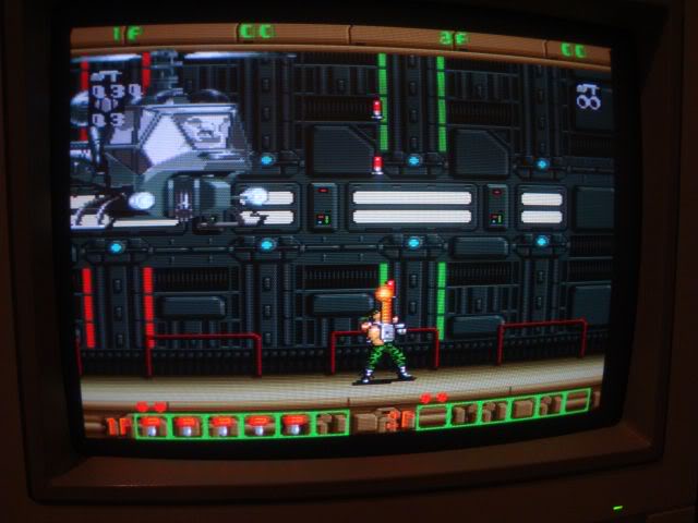
Mmmm Midnight Resistance....
A nice quick fix this one, judging by the state of the label tied to it that says "faulty" this board has probably been borked for many many years.
Board 2
Snapped up another faulty Midnight Resistance board recently, seller said the board would boot and give a blank white screen, but that the sounds were working and he could hear the game playing in the background.
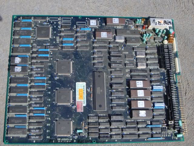
When the board arrived I gave it the old eyeball check and an empty chip socket stood out like bollocks on a bulldog,
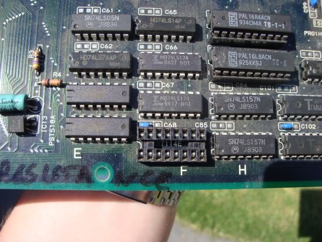
As did the fact a D880 power transistor had been snapped off.
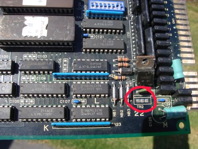
Sometimes you do get empty sockets on boards but each wasted socket cost someone a few cents so its not common on dedicated game boards (Capcom CPSx and Sega System16/18/32 often do have blank sockets depending on the game).
Anyway I have a couple of other MidRes boards so I knew what chip should be in that socket, and could borrow one to get this board up and running. The transistor wasn't a problem, its emitter was tied to pin 8 on the JAMMA edge connector, which is not used in the standard spec, but the MidRes manual says this is used for the coin counter, basically the transistor is there to provide a high current pulse to the mechanical coin counter, so its absence was not likely to be an issue.
Was a bit annoyed with the seller though, as the game clearly was not running, no sounds (just amp buzz ie amp was good) and the scope showed the 68K CPU was doing nothing, it shits me boards arrive in a different faulty state to how they were described in the sale. I actually went back to the ebay photo to see if this was the actual board on sale, could make out the missing chip and the texter writing on the amp heatsink so its clearly the one he meant to sell.
Anyway with the borrowed MB7116 PROM in place I got a screen of crap, sometimes coloured, but usually just black and white, board still wedged tho.
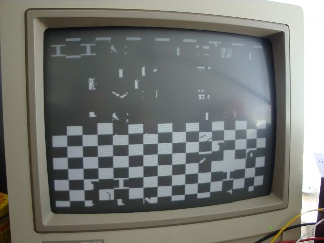
Went over the CPU again with the scope, it had volts, a healthy clock and the reset pin was high (i.e. CPU didn't have the handbrake on) - all good! However the "halt" pin was low, meaning the CPU had crashed, pretty much anything that causes the CPU to get scrambled or corrupt instructions will cause a crash and that could be anything like track damage, bus logic failures, bad RAM or bad ROM. The board is in very good condition with no signs of track damage, also no flaky F 245 or 273s across the CPU buses. So I started to dump the ROMs and compare with the MAME set. There are 4 27c512 ROMs near to the CPU which contain the program code, the first three tested fine, the fourth also tested fine, but only after I fixed what I found as I removed the chip from its socket. Without this pin the 4th ROM has no power so its not surprised the program code was corrupted.
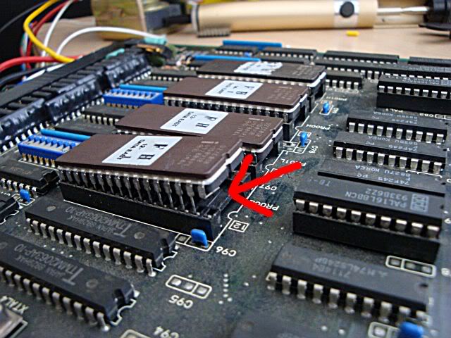
The game would boot and run after this was fixed, sound an all. Pulling the PROM out again gave back the fault the seller described, blank coloured screen but audible signs the game was running. It seems that the seller had tried to fix this himself, dumped the ROMs, found them to be OK and slapped them back in and sold the board.
Even though the game was now running it was clearly not well, half the screen was covered in white squares and there were odd fragments over the screen. Its hard to see in this photo but most of the gfx outside the white squares are fine and scroll correctly.
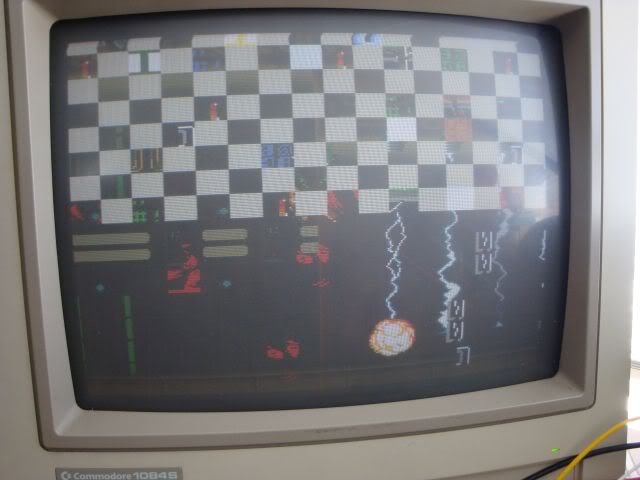
Everything was also upside down, mainly due to a dusty dipswitch that didn't work too well until it had been flipped a few times, on a subsequent reboot it decided to unflip the screen for me.
I went round the board with the scope looking for bad RAM, the sound RAM outputs looked horrible,in fact similar to the RAM that caused the fault on my other MidRes board.
All the other RAM looked fine, actually the program RAM looked a bit rough too but its not affecting the board. One pair of TMM2063 chips seemed to be involved in the fault, their outputs looked very regular (somewhat too regular) and shorting between two of the data lines on the chip RA12 at B9 caused some of the tiles to vanish and be replaced with gfx tiles that were correct.
Watch the green "I" in the white block
Normal
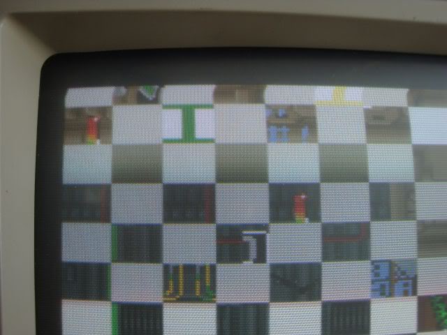
Shorted - the right gfx data appears..
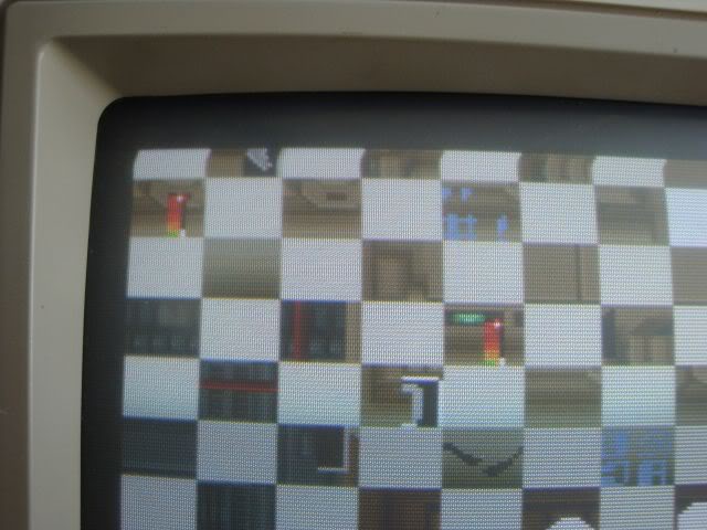
I desoldered both the gfx SRAM chips, and also the sound RAM, but all three passed the TMM2063 tests on my VP-280 reader/tester. So I soldered in 6x14 pin sockets (slim 28 pin sockets are not easy to find and not cheap, but a pair of 14 pin sockets end to end work perfectly and 14 pins cheap and easy to find). Fitted one chip back in the gfx pair and one of the old gfx ones into the sound section and booted the game.
This should be the data east logo, the colours are right at least.
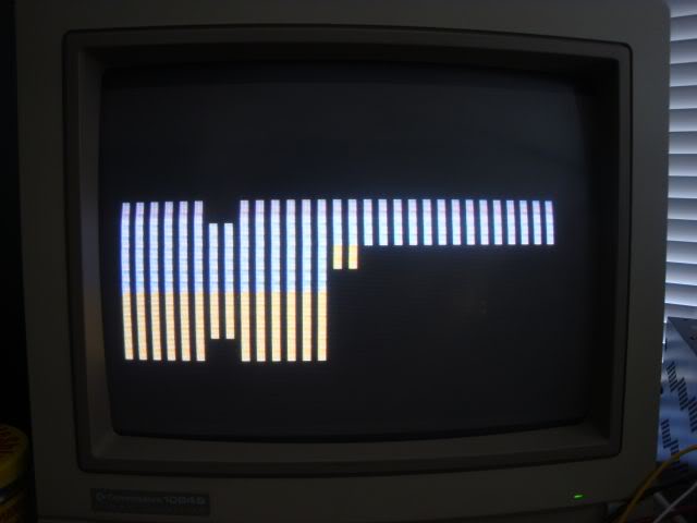
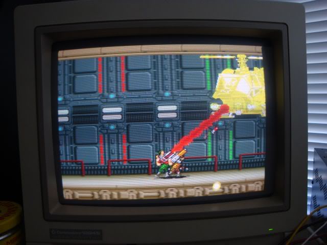
The game runs, no crap overlaying the game, but also all the "info" was missing, ammo count, number of keys collected, lives etc etc. Presumably the rubbish shown before was that info overlay system doing bad things.
I had put one of the original gfx RAM chips into the sound section earlier to see if its output was better than the chip that came from there (it was a bit), so I had the old sound SRAM chips on the desk. I dropped that into to the empty gfx SRAM slot to see what the effect would be, to my surprise the effect was that it fixed the game. I was expecting a similar fault to re-occur, in fact when I put each chip back into its original position I really did expect to see the same fault return, but it didn't.

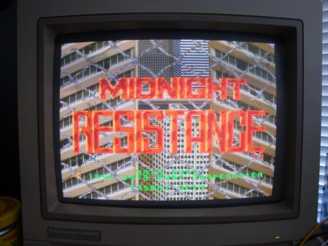
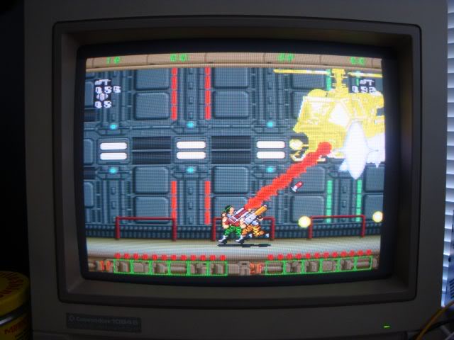
Unlikely as it seems, somehow the violence of being desoldered followed by a test in my tester has cleared the fault in the SRAM chip. The outputs are no longer "too regular for my liking" and I can get similar faults to the original by interrupting the data pins now.
Will leave the original chips in the new sockets for the time being, if they play up again they will be binned.
The only other issue I have is finding a replacement for the 7411 PROM, but other than that shes fixed!
Board 3
Got a couple more faulty Midnight Resistance boards recently, this one did this on power up, totally frozen screen of rubbish and a gentle two tone warbling noise from the loudspeaker.
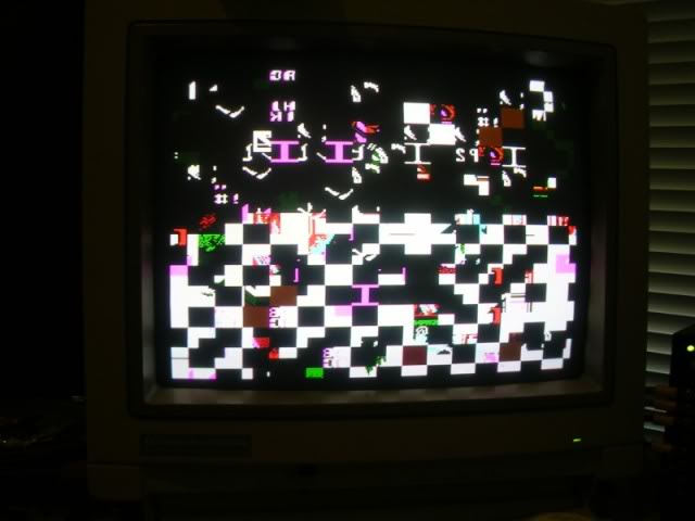
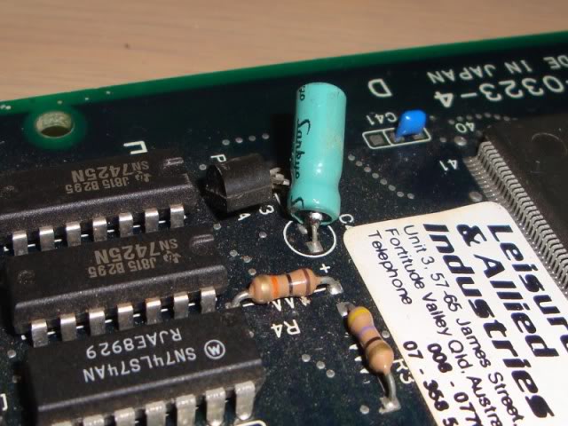
The board itself was in pretty good nick, one wrenched cap..
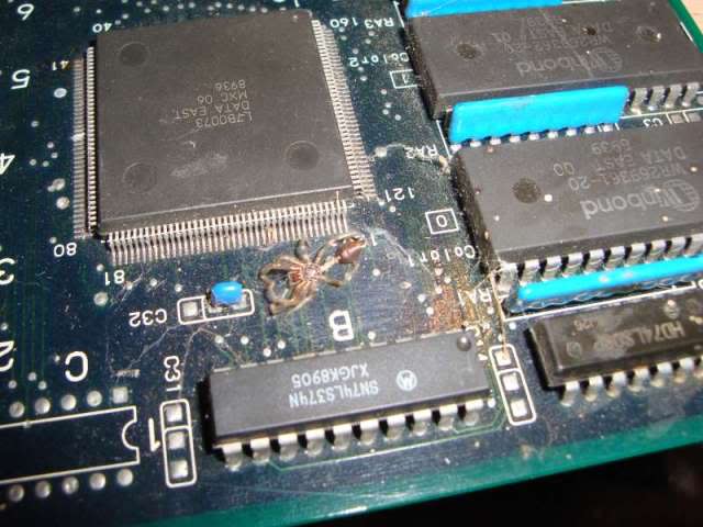
...and the carcass of a previous inhabitant in a rather webbed up corner.
First off I fixed the cap, sometimes these are involved in the reset system on the board but it was a fair way from the 68000 so not that unlikely, plus the reset pin on this board's CPU was stable in "not reset".
Having fixed a few of these now I knew that the screen of crap is what the board does when it is missing all or half of a bank of RAM comprising two TMM2063 chips at 11K and 12K ..
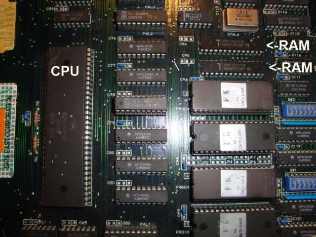
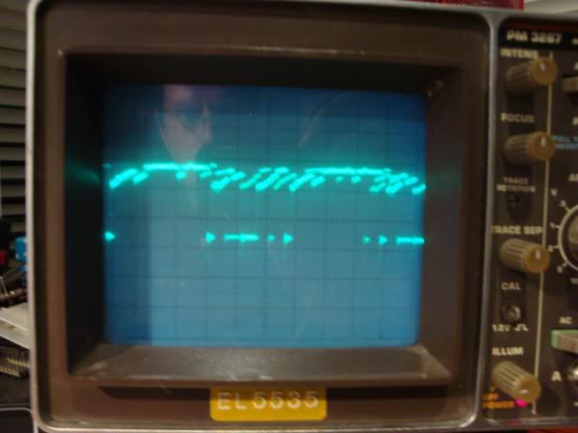
So I pointed the scope at the output of the two RAM chips and it was crap on some pins and awful on others.
So I desoldered both chips and put them through the SRAM test for TMM2063s on my EPROM reader. One could not be written to and the other gave an error saying the D6 and D7 pins were missing, so no longer connected internally it seems. What was odd was that one pin on the SRAM chip had been cut and soldered back in place, this is a common test trick to isolate a pin without removing the chip. You cut the leg off leaving enough of a stump on the chip to solder up the cut later.
So I fitted some machined pin sockets and a couple of Sony CXK5864 chips from a scrap board. Fired it up again and got the same fault.
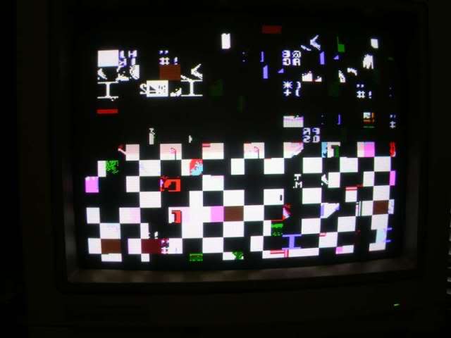
So I pointed the scope at the address bus for that RAM pair, which it shares with 2 EPROMs and 2 mask ROMS, a few of the lines looked pretty knackered too..
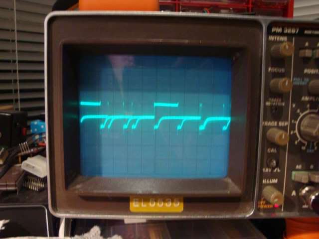
Have seen this pattern a few times before where the bus transceiver chips either loose the oomph to drive the downstream chips from logic 1 to 0 or the downstream chips are faulty to the extent that they take more grunt to drive them. Often chips will actually pass tests out of the board but the original system on the board is too weak to drive them. I pulled all 4 ROMs, read them and they checked out against the MAME set, proved they held the write data but not that the chips were really in spec. Also pulled the new SRAM chips out again and pointed the scope at the address lines on the now totally naked bus, the same wrecked signal was present. Traced it back to a 74LS245 at K21, its inputs were clean, but some of the outputs were in the state in the above photo. Replaced that chip, and the address bus lines all looked healthy, so I put the ROMs and the RAM back in and powered it up.
The game booted, but there was a problem, when MidRes boots it should show the following screens and then go into the title screen for 15 seconds or so, and then into the game demo.
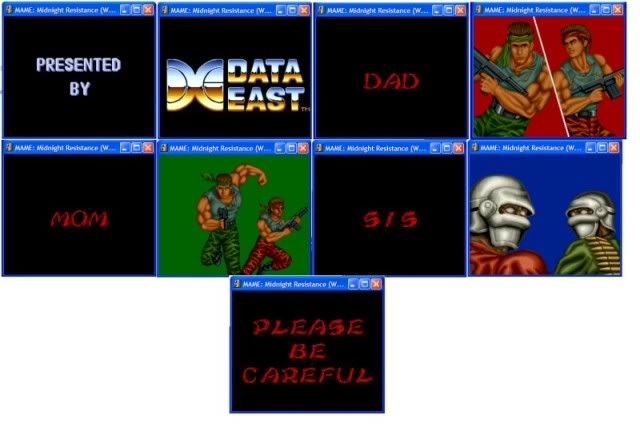
However this board showed a black screen for 10 seconds, then showed the split screen with the two fighters on the red background, then black again for 5 seconds, then the two fighters on the green back ground for 5 seconds, then black again etc. Every screen with text, plus the Data East logo was missing, I was only getting screen 4, 6 and 8, plus the delays while the others should be on-screen.
Once it finally got to the parallax scrolling splash screen all the text was missing, the "Data East Corporation 1989", and the flashing "insert coin".
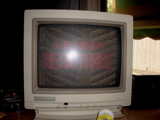
In the game all the ammo, keys collected and lives left logos were also missing.
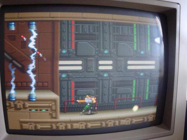
I knew from previous boards that all this is stored in 2 ROMs 4 and 5 at the rear of the board. On some MidRes boards most of the gfx data ROMs are soldered in, but ROMs 4 and 5 always seem to be socketed, sometimes they are actually EPROMs, its this pair that differ from the US, WORLD and JAPAN versions of the game, so socketted to let Data East change the versions on their stock as demand required. Anything text related is stored in these eproms and processed via another pair of TMM2063 chips at B8 and B9. Poking a scope at the EPROMs showed some decent signals and the RAM outputs looked clean. The only way to be totally sure was to de solder them and test them off the board, they both were working fine. Back to scoping around the ROMs address lines showed something that looked odd, a few of the address lines were tied low. These traced back to a pair of 74ls273s at B11 and B12, the outputs looked fine but the inputs were pretty messy. To cut a long story short the 273 inputs were outputs from the 160 pin surface mount custom at B3 and for a while it looked like the board was going to be scrap. I dug out a working MidRes and compared the signals coming from its custom and they looked identically messy to this board. I decided to pull ROM 4 and 5 out of that board to see what it did with the ROMs missing. On my board the lack of these ROMs made no difference, but on the working board all I got was a white screen with the game playing without a display. Clearly on a working board the overlay data really is overlayed, as all the data pins on the ROMs were tied high via resistor networks when the actual ROMs were missing it would appear to the game as if the ROMs contained all 1's, which would be full RGB at all points of the screen - whiteout!!!
So I went straight for the PROM at F22 knowing when that is missing you get a blank screen. I had already tested that PROM in another board by the way. I found that pin 13 (an output) was doing nothing, yet if I shorted pin 12 and 13 together I got this...
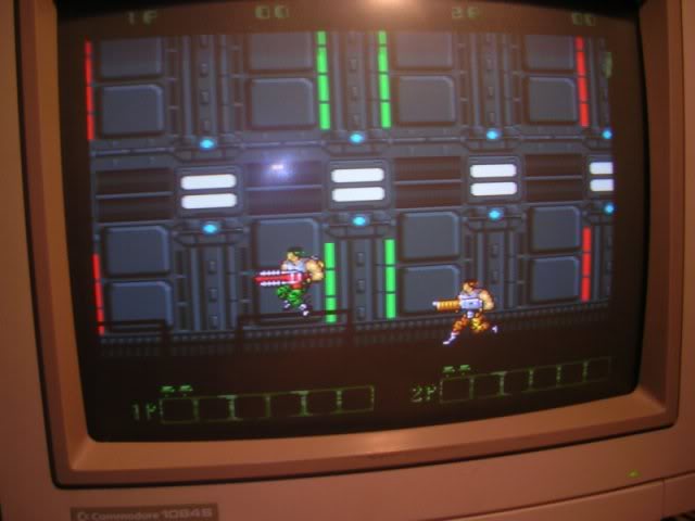
...the overlay was there faintly and somewhat corrupted. Tying pin 12 low briefly got me this...
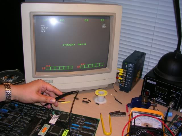
.. the overlay in its entirety, but nothing else.
By comparing the working board to the faulty one I could see that one of the address lines was doing nothing on the faulty boards prom, but not as low as all the other logic level zero signals were, this one was about a 1.5Volts higher and not very stable. Traced this back to a 7425 at E22. All of this chips inputs were healthy but its output was stuck, piggybacking a 7425 from a scrap board...
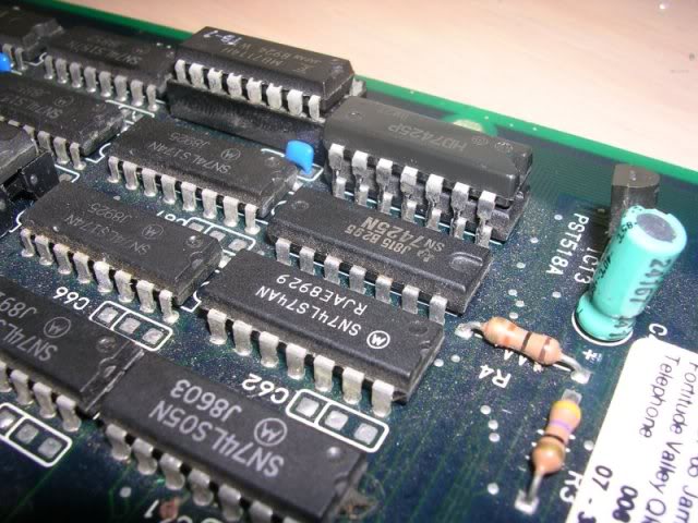
.. fixed the issue!
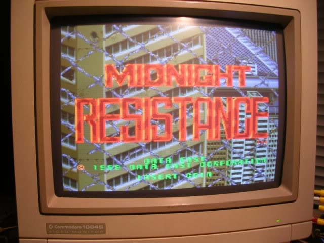
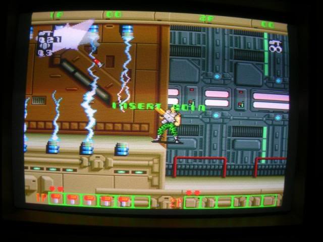
Ironic that the chip causing this troublesome fault was located right next to the bashed cap I replaced at the outset.
So I desoldered the old 7425 and soldered in the piggybacked on and the fault stayed gone.
Took the board to my cab for a test blast and found fault number 3!
The rotary control from the twisty joystick (you turn the joystick shaft to determine which way the character points his gun) wouldn't always work. Sometimes you could get half way through level 1 before it would just stop working, and other times it wouldn't work at all. The game was still running and you could do everything except aim. Thankfully this was a simple fix, the pins poking through from the ferrite beads in the path of the rotary control inputs were rather long and some had been bent together and were slightly touching. Straightening these out fixed the last problem, can play the game all the way through without a single problem now!!