PCB Repair Logs Knights Of The Round
Knights Of The Round
 |
|
| Manufacturer | Capcom |
|---|---|
| Year | 1992 |
| PCB Image | Knights Of The Round PCB |
| Pin Out | Capcom CPS 1 |
Repairer: Arcade King
Forum Thread: TMNT PCB Repair
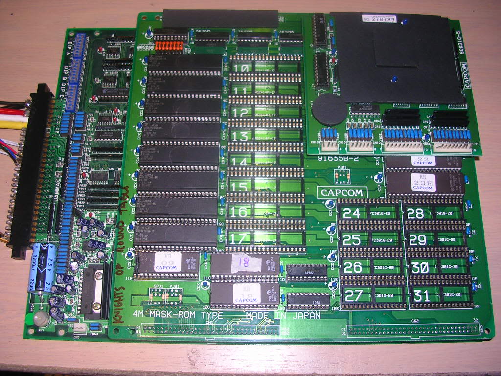
The second board I bought from Prktkljokr was a Capcom CPS1 "Knights of the Round" PCB...
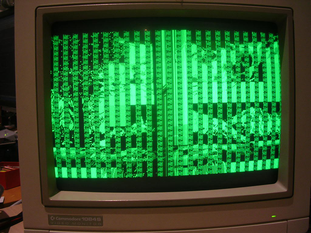
...when I first got it the game would run but it had bars of corruption across the screen. A few days later all I could get was the same screen but only the green component.
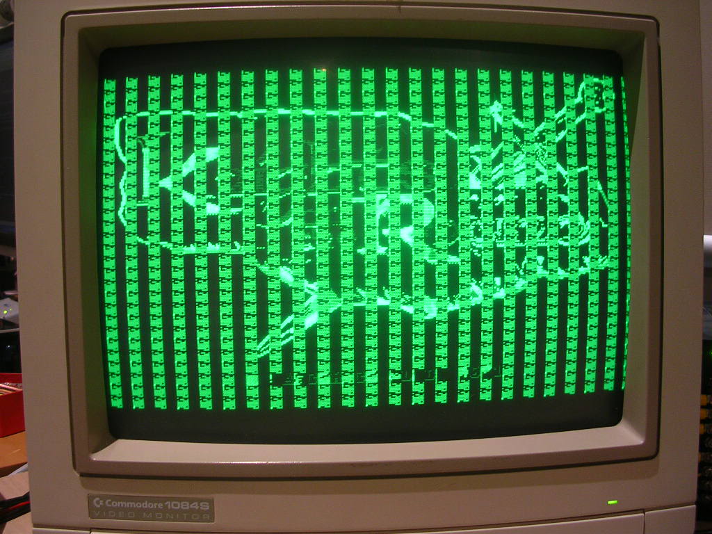
The JAMMA connection was fine, the board had just stopped producing the R and the B channel.
As I have a few CPS1 games the simplest first step is to rule out the A board, the lower board of the 3 stack, by slapping in a working game. In my case it was Magic Sword, which worked perfectly, so the A board was fine, the fault was with the B or C board, or both.
The main concern was the C board...
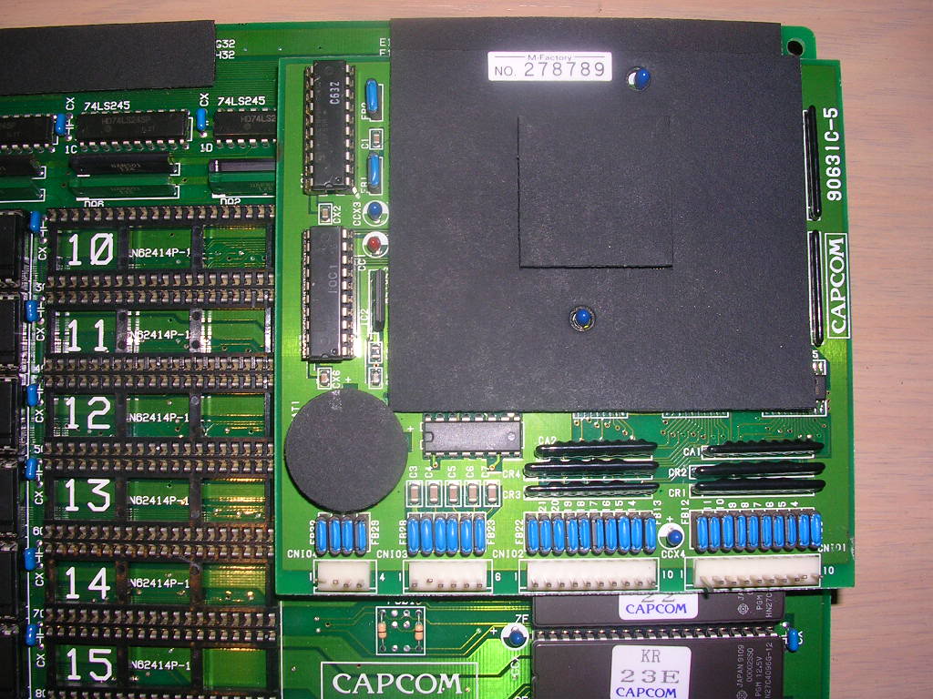
... it has a battery based suicide system and the voltage provided by the battery was 2.6V, very low. The C board was covered in a number of sticky felt pads...
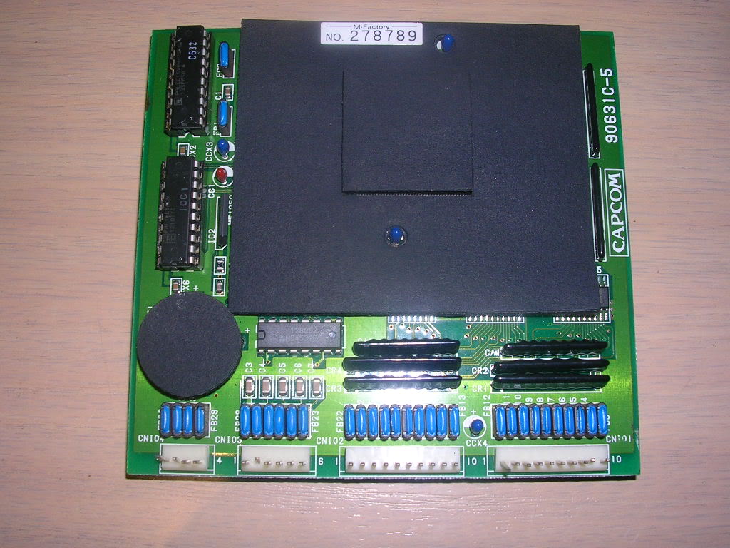
... possibly to protect the board from physical damage but also perhaps to make it harder to get to the components. Peeling it off without making a mess was impossible when cold, but fairly easy after a few minutes under a hair-dryer, only one small section remained stuck harder to the board than to the backing.
To "phoenix" these boards you need to first remove the battery, a pair of side cutters got that off...
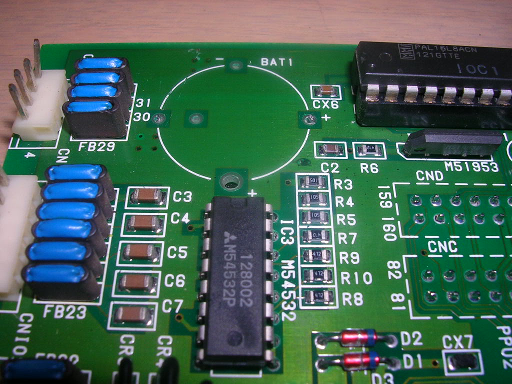
... the underside of the board was again covered in a sticky pad so it was easier to chop it off than to desolder.
The main chip was also under a pad but I had no need to remove that as I had full access to the pins, all I needed to do was to cut the tracks tying pins 45 and 46 to ground.
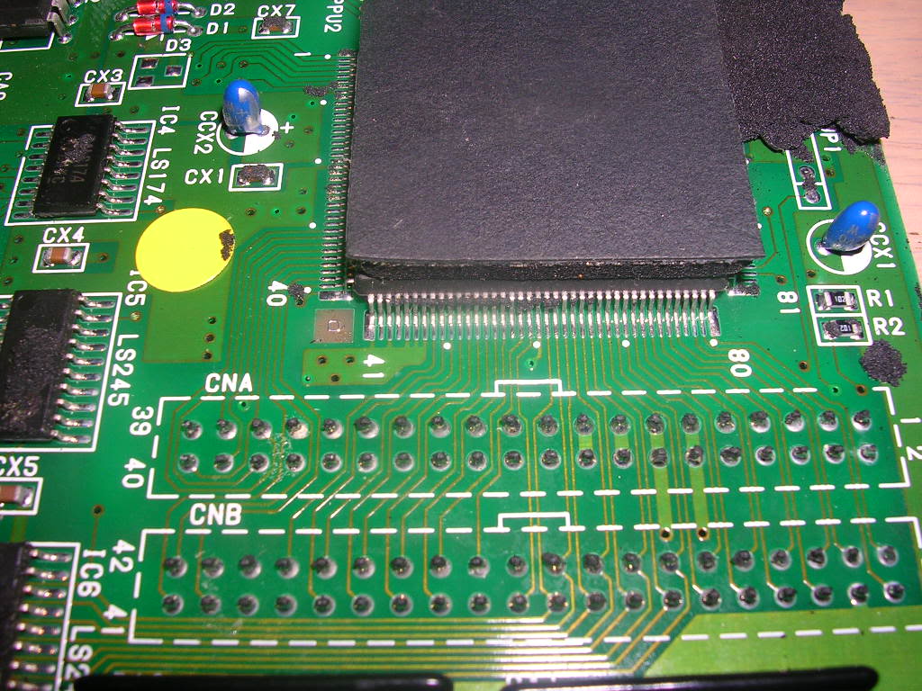
The tip of Stanley knife made a neat job of it...
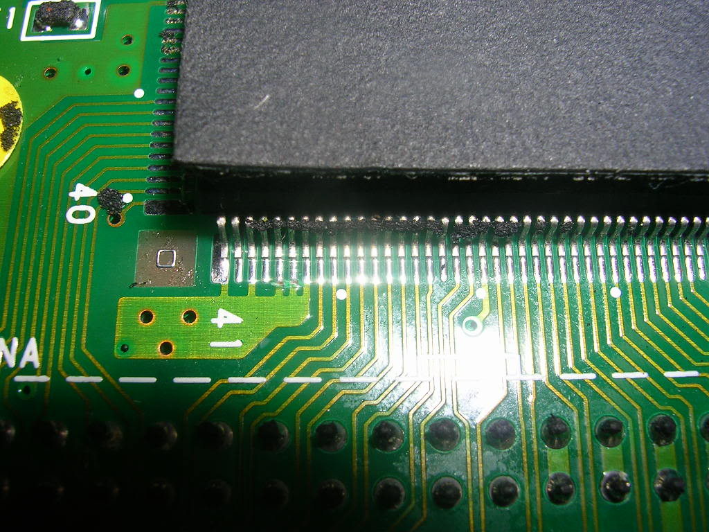
... these two pins then needed to be joined and tied high. The pheonixing instructions just said to tie these pins to +5V somewhere, personally I preferred to put a current limiting resistor in path as I had no wish for the chip to take as many amps as my PSU could provide if there was a fault with it. So I nicked a resistor from a scrap board and soldered it between the raw 5v supply and a few cm of hookup wire that was soldered between the two cut pins.
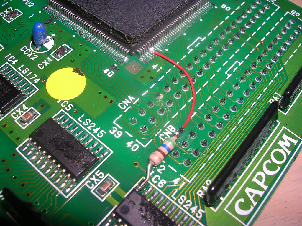
Then all I had to do was to replace the EPROM at location 23...
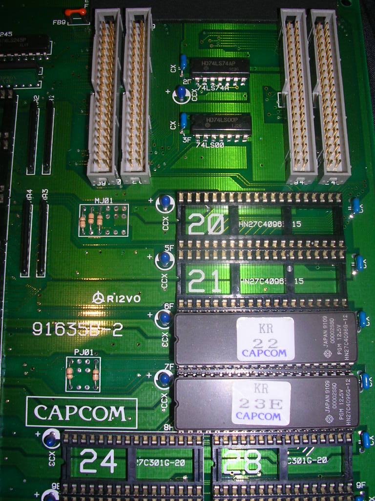
...with a 27c4096 programmed with the decrypted code. This got me the original fault back in glorious technicolour...
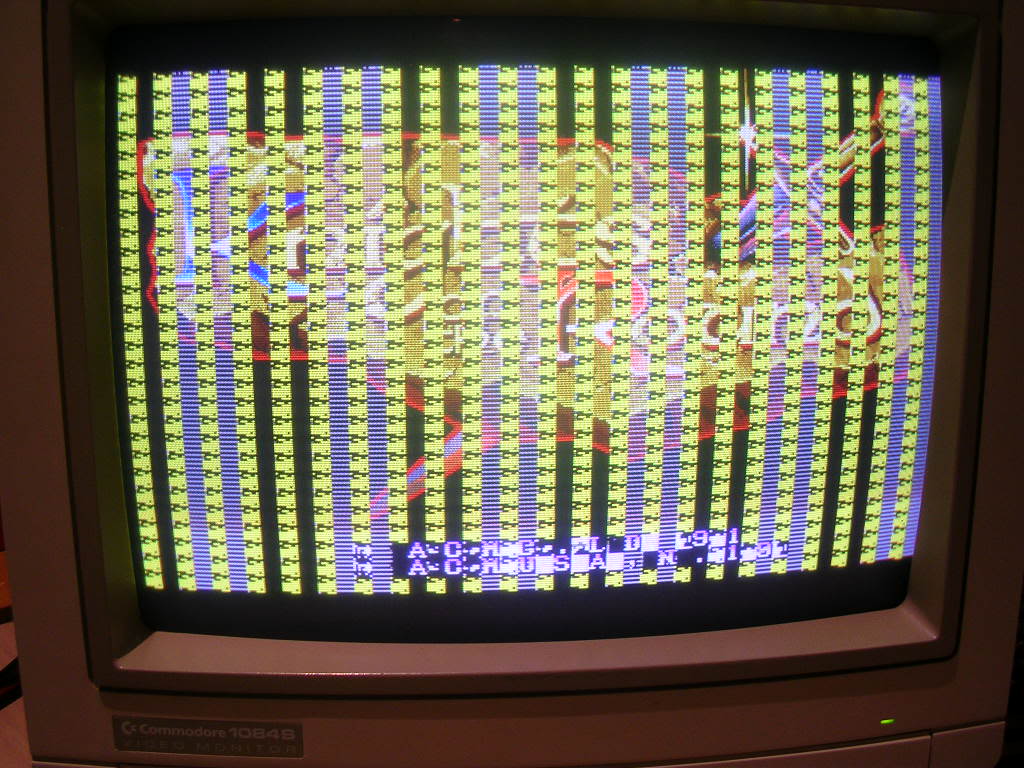
... so I am pretty convinced the board was suiciding before my very eyes prior to the operation.
Jailbars of crap smelt very much like either a RAM issue or bad mask ROMs, the RAM was all on the main board which I had proven worked fine with another game, so the mask ROMs were my chief suspect, especially as they all have very shiny legs covered in fresh scratches, someone had been polishing the legs. Not a bad thing in itself, but a good way to knacker them if you are not careful static wise.
The masks on this board were all Fujitsu MB834200B chips, which are pin compatible with 27C400 EPROMs so dumping them was easy enough. Five out of the eight were fine, number 2 had a blown /CE pin, while 6 and 8 were utterly wrecked. Removing all 3 from the board also removed all the rubbish from the screen, leaving nice clean jail bars behind.

Programming three 27C400 EPROMs with the missing data filled in the gaps and fixed the board!
