PCB Repair Logs Frog
Frog
 |
|
| PCB Image | Frog |
|---|---|
| Pin Out | Reserved |
Repairer: Arcade King
Forum Thread: Frog PCB Repair
Won this one a few weeks back.
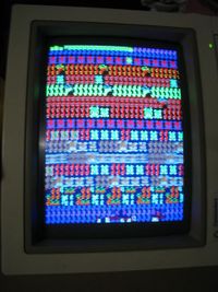
Problem: Garbage on the screen, frogs visible and game seems to be playing
Fix: Bad 2114 ram at IC86
Problem: Board decided to die
Fix: 74LS368 at IC73
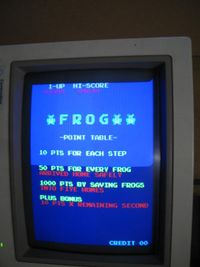
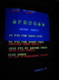
Problem: Colour of Frog wrong. Frog would have white in the center instead of yellow and showed up red at the bottom of the screen when demo on, some text was also wrong colour.
Fix: There is a hack to correct colours on this board. Pin 15 of the 74LS377(IC61) was connected to pin 4 of a 74LS20(IC36). Moving the wire to pin 5 of the 74LS20 fixed the colours on the frog.
Problem: No sound
Fixed: z80 on sound board
Problem: Background colours were wrong, top colour was a a royal blue while the bottom was a navy blue which is what the top was suppose to be.
Fix: From playing around with the Scamble to Frogger hack I learned the background colours went through a 74ls08. Shorting inputs at 4 and 5 would make the entire screen navy blue while leaving the output ping 6 out would fix it entirly. Shorting the two inputs were not a option for me so i traced everything back to a 74126. To cut a long story short there are 2 470 ohm resistors 1 above and below this 74126 chip both dictating the final colour of the background. Removing the resistor at the top fixed the colours. Both resistors look like they have been replaced.
If Klov is anything to go by FROG was a bootleg Frogger with modified colours. This board would appear to look the same as the Konami/Sega one but wont run the programs.
There was some wiring done (poorly) to a 74ls377 I now know was done to correct the colours back to how Frogger looks.
Very happy with this board, be nice if I could make it say Frogger on the title screen. Any programmers in our little group feel like some hacking?
Repairer: dav000616
Forum Thread: Frogger (Bootleg) PCB Repair
Brought this off ebay 12mths ago and almost got burnt on the deal but that's another story. Hooked it up and got nothing but a blank screen.
The board layout was identical to the sega frogger schematics so I used this for reference. I hooked up my sega board and made note of the control pins on the cpu. For memory there were 3 pins, BUSAK, BUSREQ and WAIT that were different.
WAIT was held high instead of high low pulsing so I started here. Traced Wait back to a 74ls161 at IC82 which has pulsing inputs but no outputs. Piggybacked a 74LS161 and turned it on, still didn't have a picture but the outputs were pulsing now and I saw a small horizontal flicker of video so I cut the 161 out and soldered in another and it now lives.


