PCB Repair Logs Ghost'n Goblins
Ghost'n Goblins
 |
|
| Manufacturer | Capcom |
|---|---|
| Year | 1985 |
| PCB Image | Reserved |
| Pin Out | Reserved |
Board 1
Repairer: GameDude
Forum Thread: Ghost'n Goblins PCB Repair
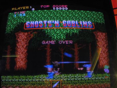
Had a problem a month back my Ghost n Goblins decided to play up.
All sprites were upside down but only in the sprite block, in other words the knight for example had his feet trampling his head.

I had a spare board so with this I narrowed the problem to the video PCB (of course). The left side handles backgrounds the middle handles sprites and the right side handles some other crap... cant remember now.
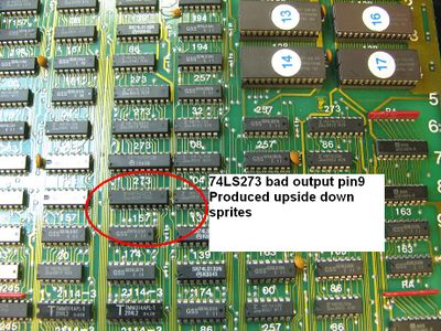
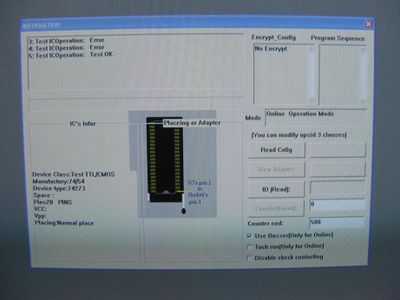
I started looking at the 273's and it did not take long to find one with a dead output on pin 9 at location 8J. I removed the chip and tested it in my USB tester and sure enough it failed, I then confirmed a worker and reinstalled the IC and tested.


For this repair I mainly used a logic probe and the ttl handbook so I could see the pinouts as I could not find the schematics for this PCB if anyone has it PM me so I can add it to my collection
Board 2
Repairer: VectorGlow
Forum Thread: Ghost'n Goblins PCB Repair
All boardsets referred to in this repair log were Capcom originals
Symptom: Background broken up – video board fault
Cure: No input on pin 11 of the LS157 at location 9B – track broken somewhere between it and pin A18 of inter board connector CN1
Symptom: Text sometimes scrambled, corrupted – top board fault
Cure: No output from pin 8 of the LS32 at location 9D
Symptom: Background doubled up – video board fault
Cure: Broken track between pin 19 of the LS273 at location 10D and pin 11 of the LS283 at location 10B
Symptom: Black, pixel high, horizontal stripes through all sprites – video board fault
Cure: Bad 2114 at location 12H – replaced 2114
Symptom: Top halves of all sprites apparently missing, but on closer inspection it appeared that anything that entered the horizontal plane (head height within the game) then briefly disappeared – video board fault
Cure: Pin 14 of the LS175 at location 8E was stuck low – replaced IC
Symptom: Blank white or black display, sometimes flickering or garbled characters briefly appear, but the display is usually blank – video board fault
Diagnosis: It’s possible to run just the top board on it’s own (to a limited degree) – this displays slightly more normal data. However, as soon as the video board is plugged in the fault occurs. Noticed that the black inter-board edge connector CN1 had some excess solder on the underside and creeping under the connector where the pins could be seen (someone had tried to re-flow the pins), and with a multimeter found a bridge between pins A18 and B18 – removed that connector and removed some excess solder that was bridging some pins between the connector and the PCB, replaced the connector, so fixing the fault
Cure: See diagnosis
Symptom: Sound isn’t loud enough – top board fault
Cure: 100uf 16v electrolytic cap (connects to pin 2 of the main sound amp) wasn’t making good internal contact on one leg (had been knocked). Replaced
Symptom:Cure: Music is missing some notes, sound f/x a bit off – top board fault
Cure: Bad YM2203 at location 14E - replaced
Symptom: Slight buzzy hiss on the sound – top board fault
Cure: Dodgy LM324 amp at location 12D – replaced (note: if this LM324 is removed/has failed completely then the sound f/x are still present but there’s no music)
Symptom: No background trees, etc – top board fault
Cure: No output on pin 6 of the LS20 at location 1F - replaced
Symptom: Sprites have chunks missing from them of varying shapes and sizes – top board fault
Cure: Slightly corroded legs on PROM at location 2E – cleaned off corrosion
Symptom: ‘ground’ background tiles misplaced and the wrong colour, also the knight can end up walking in mid air – video board fault
Cure: Broken connection between pin 4 of the LS273 at location 12A and the inter-board connector pin A2
Symptom: Bottom half of the screen reproduced in the top half, plus game crashes during attract sequence – top board fault
Cure: No output on pin 11 of the LS161 at location 1L – replaced IC – this fixed both faults
Symptom: All sprites VERY broken up and partly ‘scattered’
Cure: Bad 2114 at location 11E on video board – replaced
Symptom: Horizontal lines through all sprites, plus sometimes a part of a sprite appears slightly offset elsewhere
Cure: Bad 2114 at 11H - replaced
Symptom: Vertical black lines through the top 7/8 ths of the background, along with light brown bars besides the black bars in the top line of the score info
Cure: Bad LS194 at 4A on video board
Symptom: No red
Cure: Bad 2148 at 6D on top board
Symptom: No Blue
Cure: Bad 367 at 8C on top board
Symptom: No sprites, but moving the boards sometimes caused them to partially or completely appear
Cure: Bad connection on pin 16 (+5volts) of the LS174 in column F (and edge connector side) of the top board
Symptom: Board won’t power up – just gives intermittent flashing coloured horizontal strips, sometimes a blank white display which variably breaks up (original Capcom)
Diagnosis: Checked the inputs to the 6809 CPU and found no clock input on pin 38. Traced back through the circuit and found dead outputs on the LS367 at location 1J (pin 7 is the clock output to the CPU and other ICs)
Cure: Replaced LS367 at location 1J on top board and boardset booted up correctly
Colour info:
On top board:
Red goes via the 2148 at 6D to the 367 at 6C to the resistors R1 to R5 then to the edge connector
Green goes via the 2148 at 7D to the 367 at 7C to the resistors R6 to R10 then to the edge connector
Blue goes via the 2148 at 8D to the 367 at 8C to the resistors R15 to R19 then to the edge connector
Player 2 controls info:
Go via the Capcom CR084 (resistor pack?) to the LS367 at 5A on the top board. For example, player 2 shot 2 goes into pin 5 of the resistor pack and out of pin 4 then to pin 14 of the LS367 at 5A and out of pin 13 onto the data bus
