PCB Repair Logs Defender
Defender
 |
|
| PCB Image | Reserved |
|---|---|
| Pin Out | Reserved |
Repairer: GameDude
Forum Thread: Defender PCB Repair
Got this from a fellow AA member Gavin (jumpydoctor) amongst other boards this was listed as number one priority for repair.
Having never worked on this game before I can honestly say at the very least it was interesting unit to fix, I had plenty of theory and the schematics available on the web were crap but I had help from a JAMMA+ forum member from the UK who kindly sent me a very nice hi-res copy.
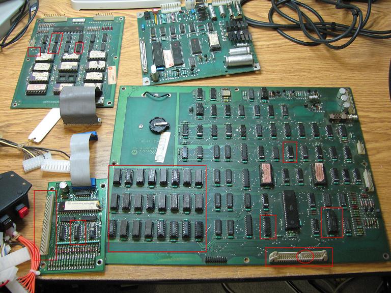
Anyway here we go as you can see in the first picture its all laid out, I have circled in red all the problem areas which were found and fixed during repair.
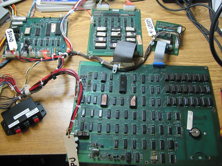
Starting top left is the ROM board, top right audio, bottom left is the IO widget board and bottom right is the main CPU board.
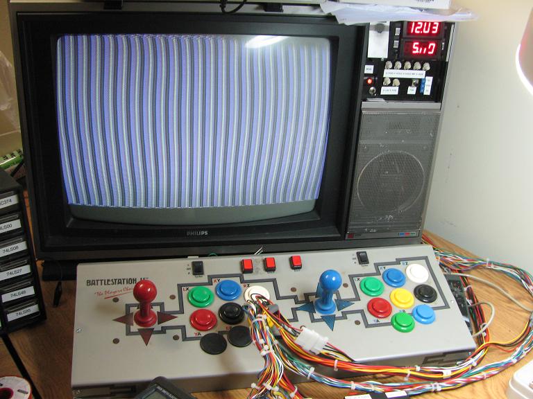
OK first thing on the list was a full inspection, Jumpy had already informed me of a bad ram socket that he had replaced and I also noticed a pin missing on the 40pin connector for the ROM board, apart from that it looked reasonable. Connect it all up and the screen was not exactly what I wanted to see, static vertical lines.
Using a logic probe it was easy to see that the watchdog was barking, at this stage I decided to repair the missing pin on the ROM board connector. I pulled a pin from a broken Capcom CPS1 A board which has exactly the right size pin needed to replace the broken one.
I then moved to the ram sockets, they didnt look good and had all sorts of ram installed so I decided to remove the ram first and this is what I found.
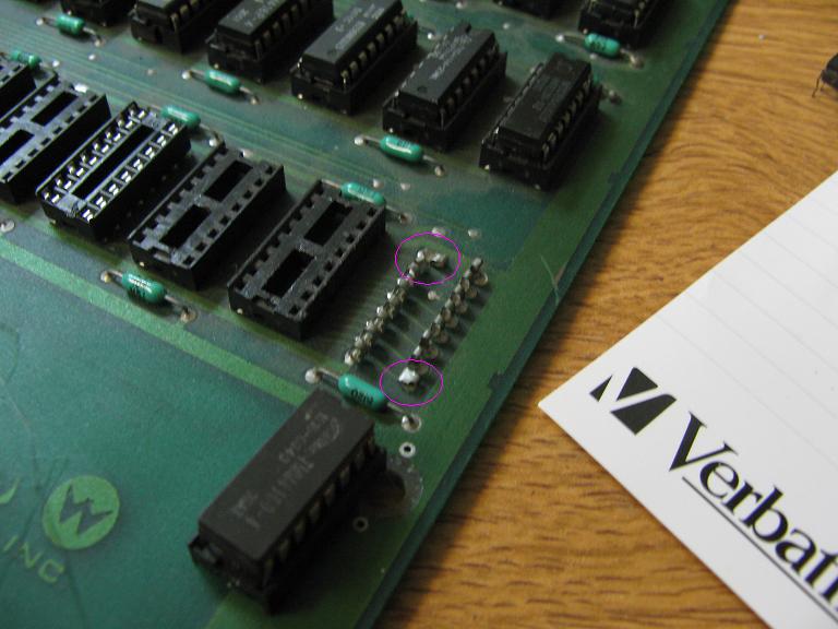
As you can see the pins were stuffed. At this point I decided to replace all ram sockets just to be sure (I later found two other bad sockets).
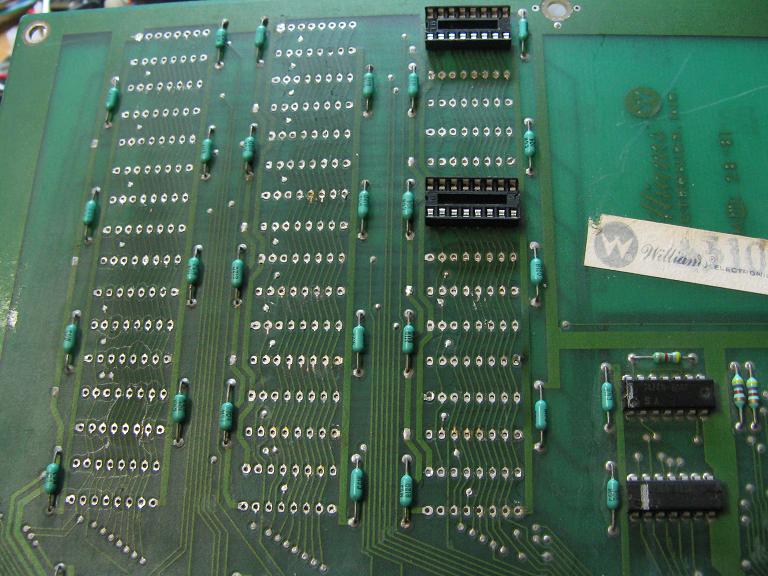
And then replaced them with nice new ones.
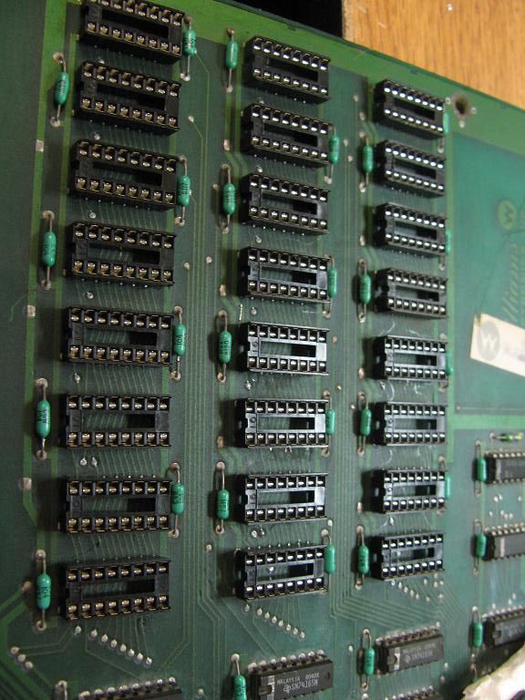
After this I tried to power the unit again. No go POO not even a small change. At this point I asked Jumpy where this set came from and what was the history. It ended up being a "worker" from EGAY and not even the one that was in the picture.
Great... I suspected there may be multiple faults from someone swapping out dead boards so I moved to the FLUKE to run CPU board tests. I disabled the watchdog and plugged in the FLUKE and ran a ram test. Instant fail everywhere ran a ROM test and all signatures came back the same crap.
OK so disconnected the ROM board for now so it was not interfering with anything on the bus and decided to work on the ram issue, there was one 74LS245 at 1K which did not look right and was the only buffer connecting the DATA BUS to the CPU. I replaced the 74LS245 and ran the RAM test again on the FLUKE.
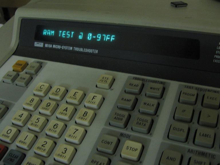
The scripts that are run on the fluke are real handy and are created from the QuarterArcade tech website, if anyone wants to know how to use the scripts PM me. It gives live feedback on test progress on a PCB without the need for video output on the game.
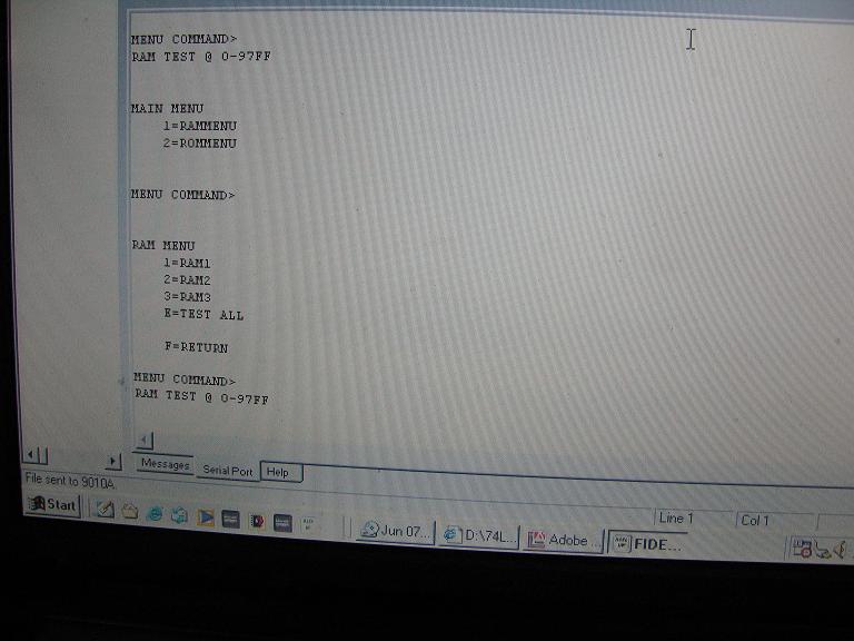
I was getting all excited as the ram test was going through. As can be seen on the screen when video memory is written to it changes the display.
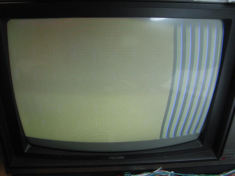
However halfway through the test (they are long) I started getting read/write errors. Setting the FLUKE on loop revealed that sometimes it would read OK then not again. Hmmmm....OK this took a little while to find but I eventually found the culprit. It was a 74153 (not the LS type) at 4H according to the schematics and I found it by using a method of cooling and heating the IC. When this was done I noted that the loop test almost always was OK when cold and went real bad when hot. I also noticed that at 4.8volts it took longer than at 5.2volts to produce a fault in this chip. It took me a while but I found a replacement and BINGO! ram test now pass!
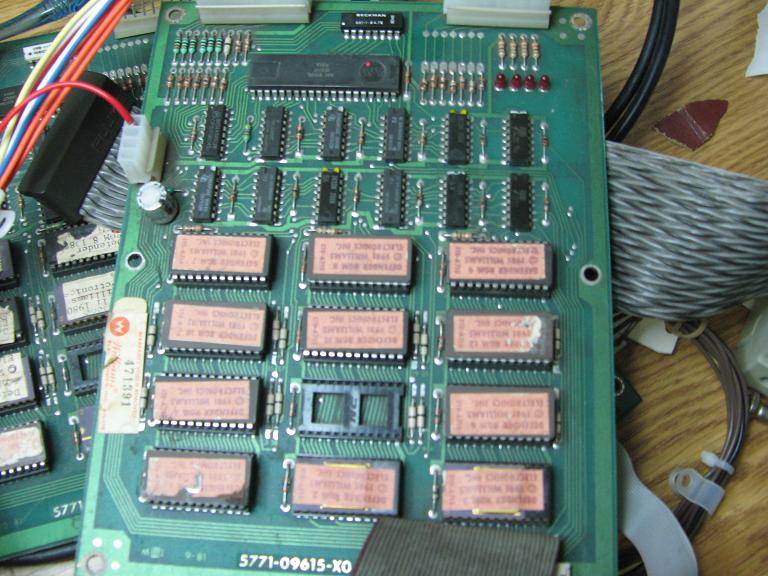
Moving on now to the ROM board and the FLUKE still could not ID the ROMS and when powered up I got a grayish rug pattern and still no boot but a hell of alot better than before. As luck would have it I had a spare ROM board (red label) and plugged it in.
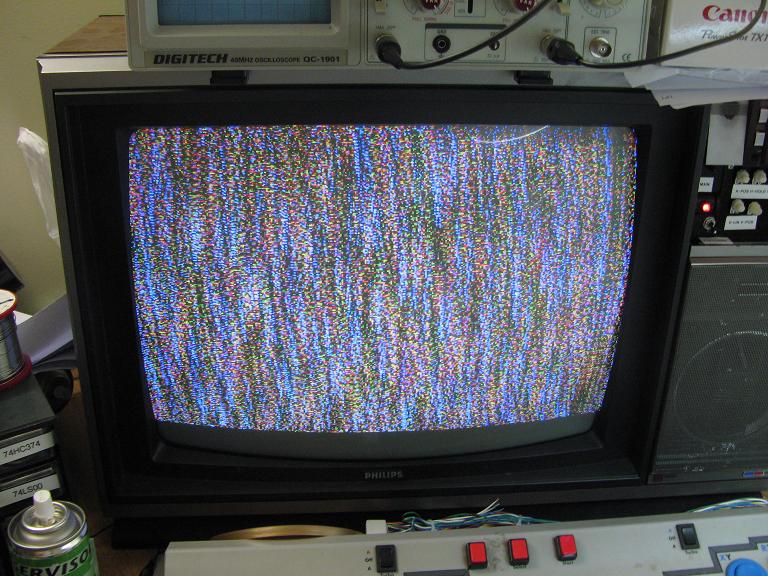
WoooHooo rug pattern! Thats good as thats the startup test the game does before play.
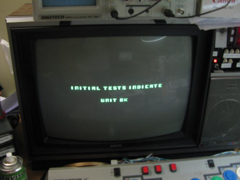
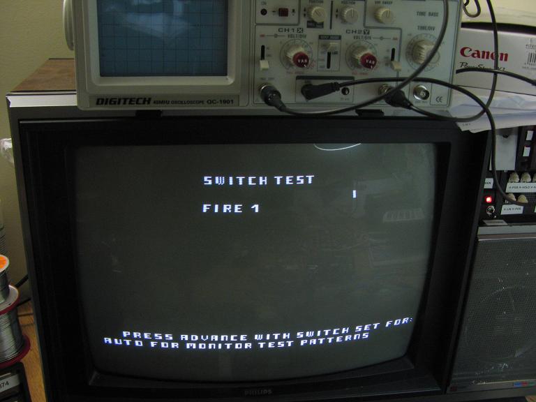
All was looking good however the game went into bookkeeping (a form of game data storage) which uses a battery to power a 5101 CMOS ram chip located at 1E.
I noted that some of the values stored were '?' and some were '0' clearly this was not right and upon saving the game would not exit.
John from Johns Arcade saved the day and sent me a shiny new 5101 to slot in (THANKS JOHN)
The game now saves and exits from bookkeeping and the game demo starts. I coined a game up but nothing happened. Random mashing of buttons proved that some signals were getting through but clearly not the way its supposed to be. Using the setup buttons I progressed to the input test.
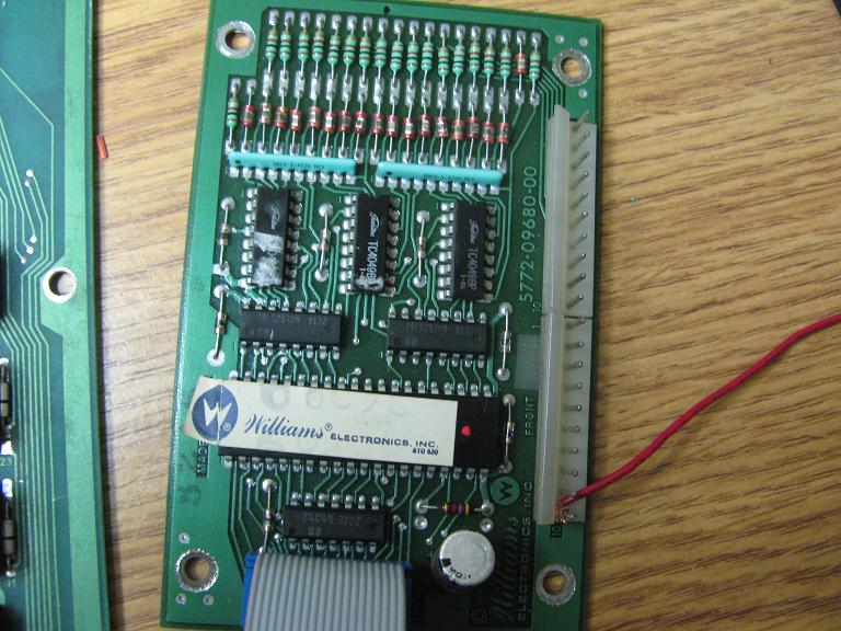
Clearly there was a stuck input BUT something else was wrong. Pressing each button cam up with the incorrect input. This had me stumped for 5minutes until I looked up some pictures of various IO boards for williams games and found out this board was not a defender IO but a Stargate/Robotron IO board. Essentially the same except for one important fact, Defender pin out is reversed compared to all other IO boards.
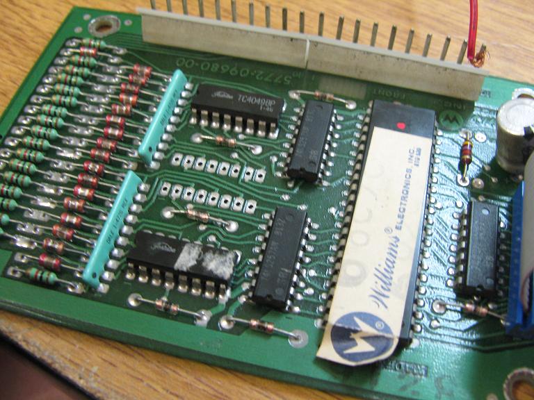
After rewiring the harness to match I made all buttons do what they should but the stuck input was still there. This turned out to be a bad 4049 CMOS Hex Inverter at IC3. I found it by tracing the signal back through the circuit until I found the good signal/bad signal.
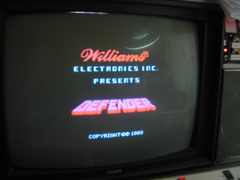
Replacing this fixed the input problem.
The ROM board turned out to be a real pig. Since all ROMS signatured the same I assumed it was something to do with the chip select signal. After checking all ROMS had good sockets and replacing a missing filter cap I used a logic comparator to compare IC's a bad 74LS139 was found and replaced but still problems. Checking the schematics I followed the chain for chip select and noticed data goes through IC 17 74LS395 and then is split by an 7442, using the logic probe showed dead outputs on all four pins of the 74LS395 and good inputs. Replacing this then showed changes but still no game.
OK checking the 7442 with the logic comparator revealed pin 1 compared badly and when verified against the working unit it was confirmed bad. Replacing this FINALLY got the ROM board working.
