PCB Repair Logs Commando Bootleg
Commando (Bootleg)
 |
|
| PCB Image | Commando (Bootleg) PCB |
|---|---|
| Pin Out | Reserved |
Repairer: kane
Forum Thread: Commando Bootleg PCB Repair
Here's a Commando bootleg pcb, a large 3 board stack pretty much the same layout as the original Capcom. It's a nice PCB to work on as the bottom board handles the sprites and the top board the backgrounds, makes it a bit easier to track down problems.
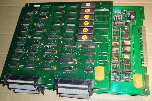
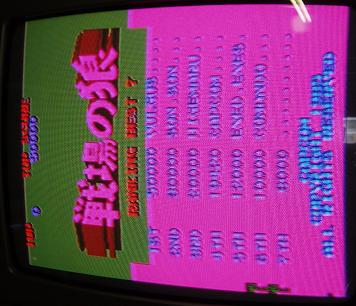
Wired up a rough harness and tested and got absolutely nothing. Zero activity anywhere on the board, I couldn't find a pulsing signal anywhere. First I pulled and read all of the ROMs and they were all good, and was the Japanese set ('Senjou no Ookami' is the japanese title which apparently means 'Wolf of the Battlefield' ).
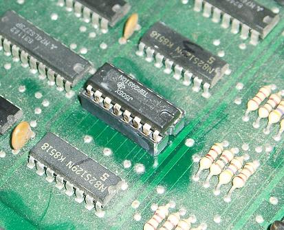
Looking over the board I found a chip at location 2D, a colour PROM, that had been desoldered and then placed back in the board, unsoldered, with a few legs bent over so it wouldn't fall out . The PROM was different than the others next to it, very suspicious. Not much I could do with it so fitted a socket and placed it back, hoping it would work.
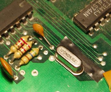
Everything else on the board looked OK, but couldn't see a crystal anywhere on the board. Looked up on the net the MAME source code for Commando which showed it required a 12 MHz crystal. I couldn't find a 12 MHz crystal on any of my scrap boards but searching through my junk (I have plenty of that) I found an old 40 megabyte PC hard drive with a newer style crystal that was 12 MHz. Fitted it to the board with a bit of tape under it to keep it off the neighbouring vias.
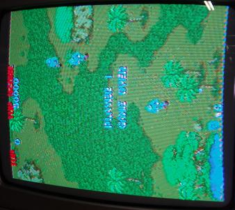
Re-tested the board and had activity now but the board didn't spring to life until I jiggled the ribbon connectors a bit (they are quite dodgy on this particular board). The game was running with sound but had no backgrounds, had sprites but they were a bit screwy and the colours were all wrong.
Tackled the backgrounds first which come from the top board, a fairly straight forward layout, 6 ROMs, a 6116 RAM and a bunch of TTLs. Quickly found a 74LS04 at location 9C with a output pin blank and a few others possibly stuck. Piggybacking it brought back the backgrounds so replaced it to fix it.
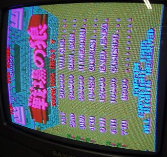
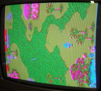
Before reassembling the PCB stack I swapped over the ribbon connectors with one another and straightened them out a bit and I think that fixed the errors in the sprites as I never had a problem with them after that. Now the backgrounds and sprites were good, but there was still a colour problem with some areas looking pink.
Turned my attention back to the colour PROM mentioned earlier as it was a good bet that was the problem with the pinks. My ROM reader can't read PROMs so I couldn't verify it was good. It was a bit of a weird problem because some parts had perfect colours, and other areas pink, a bit half and half. Running the board with the PROM removed made the entire screen have a tinge of pink, so it looked like the PROM was 'sort of' working.
Reading the MAME source again, the 3 PROMs at locations 1D, 2D and 3D are the colour PROMs red, green and blue. I done a bit of messing around in MAME, substituting in a blank file for the 2D PROM and was getting the same pink, so the problem was definitely related to the PROM.
Each of the 3 colour 82s129 PROMs have 4 outputs that go through 4 resistors then combine into one and run to the edge connector for Red, Green and Blue. On my suspect PROM, one output at pin 9 was shorted to ground. The board traces (and my socket soldering ) were good, but with the chip removed from the board, pin 8 (ground) to pin 9 (output 4) was shorted internally ie. knackered, or not programed correctly.
I got AA member Skybeaux to program a new PROM that I received today, and that fixed all the remaining colour problems, thanks Ken!.
