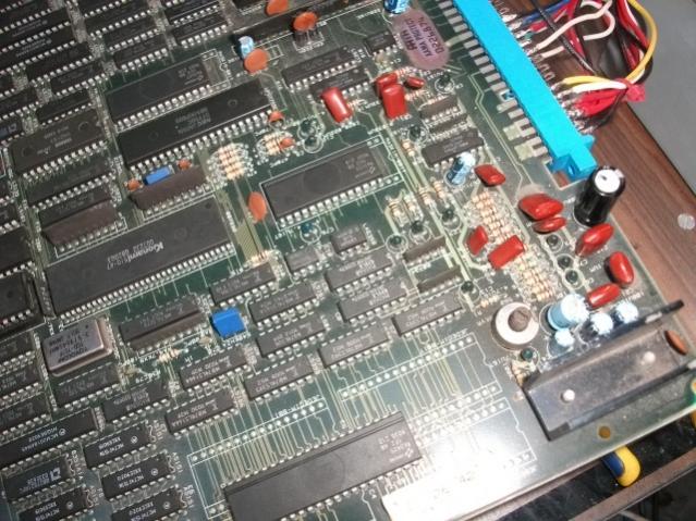
PCB Repair Logs TMNT Teenage Mutant Ninja Turtles
TMNT - Teenage Mutant Ninja Turtles
 |
|
| PCB Image | TMNT PCB |
|---|---|
| Pin Out | Reserved |
Repairer: Arcade King
Forum Thread: TMNT PCB Repair
TMNT donated by Joe
Board problems:
Vertical Lines in character graphics.
vertical Lines in background.
When put into test most Mask Rom k27 and H4 come up as bad.
Found a dead Data line pin 28 Q15 socketed and replaced mask rom with a 27c400 4 meg eprom. Background is now perfect.
Replaced the Mask Rom H4 with another 27c400 and fixed the Character Graphics.
Only problem remaining with this board is missing TMNT theme song.
I've concluded the mask rom D5 contains the intro song and its dead. I've found 2 dead 74ls393s which are connected to its address lines. Replacing those chips bring back the intro but its repeating and not in full.
Changing the mask rom @ D5 fixed the intro song and the board is now 100%!
TMNT board 2 from Joey
When you turn this board on you get a white screen which will flash after a few seconds. What it is actually doing is running the ram, rom test.
I probed around a bit and found the two 2018 rams were not outputting anything through the data lines.
Piggy backing some other 2018 rams I could just make out the ram rom screen with rams F22,F23,G27 and G28 registering bad. Thinking the rams were bad I started by removing F23 and F22 put some sockets in and fired her up. Didnt really change much, the ram error is still there.
Turns out the rams were fine. The only reason I could see the test was I was using slower 35ms rams where the board requires 45ms. Comparing with a working board it would see the CE,OE and WE are not working as they should.
The WE traced back to a 74ls32 pin 6. This chip enables data output to the 27ls245s connected to the rams and the WE as well among other things. The chips appears to be fine but once again comparing it to a working board the inputs at pin 2 and 5 are not pulsing when they should to enable the rams. Traced it back to a 74ls138 @ H25. The outputs were doing jack. Replacing the chip fired up the board although there is massive graphics and PCM sound corruption which is bad mask roms, the intro music is working but like the board above its all messed up. I've ordered some more 27C400.
Got the 27c400s and the following mask roms were bad, K27, H27, K4, D5.
Graphics and Intro music are 100%. The voices in game are not working and only a loud screech comes out. Being lazy I naturally assumed it was the 1 meg mask rom. Replaced it with a the equivalent Eprom 27c1000 but no change. Note to self. check the address lines MORE carefully. Problem was a broken track under the D7759C synthesizer chip. Pin 35 on the synth chip to pin 3 of a 74ls273 @ B16 was broken. Repairing the track fixed the sound.
TMNT board 3 from Joey
Problem: No Sound
Fix: Put the right amp on next time Joe
TMNT from Tom
Problems: Board constantly resets.
Fix: Found 2 dead ICs a 74ls107 @ G16 and 74ls74 @ I20
Problems: Board now boots up with Bad F22 and F23
Fix: Tracked some dead address lines back to a 74ls157 @ D25
Problem: board now boots but to the warning screen but hangs and resets with random voice sounds.
Fix: The CPU was socketed and I noticed was a 68010P8, Replaced it with the propper 68000 game now runs but with graphics corruption.
Problem: Graphics corruption in the background and characters.
Fix: Doing a mask rom test roms @ K27 and K4 are bad. Replacing them fixes the board.
TMNT Virgils
Problem: Corrupted Background graphics.
Fix: Mask roms test reveals bad H27, replacing rom fixes problem.
Problem: no in game voices, EG: Fire, Attack, hang on April etc.
Fix: Dead D7759C synth chip.
Board Originally had a bad mask rom @ H27. I didnt have any replacement roms at
The time so I put the PCB to one side. 3 or 4 months later I turned it on again and it had rows of zeros all over the screen in vertical columns. You could see in the background bad ram error.
Problem: Zeros all over the screen, Boot up tests indicated bad rams G28 and G27.
Fix: Replaced both rams board comes up ok.
Problem: Vertical lines in graphics.
Fix: MAsk rom test has H27 as BAD. Put a socket in and replaced rom. Only 3 original mask roms left on this board.
Problem: In test some 4 player and dip switches stuck on.
Fix: Bad 74ls253 @ D28. All these 253's are F(Fujitsu) IC's and they will all eventually fail. VERY common problem.
Problem: After a few minutes some of the sound starts crackling and fading out.
Fix: Faulty LM324 @ G 12. another common fault.
PCB now 100% until next time I decide to test it in a few months time.
2nd of my boards
When I plugged it in last I couldn't get into the dip switch settings now its developed more faults.
Problem: Displays ram F22 as BAD
Fix: Faulty 74ls245 @ C24
Problem: Dip switch set 3 not working.
Fix: Faulty 74ls244 @ D27
Game runs ok but after awhile developed more problems
Problem: Colour "flaky" particularly noticeable in the Purple in Donitellos square in the game into.
Fix: Faulty 74ls273 @ E23
Game ran ok for awhile again then developed more colour problems.
Problem: I noticed below the manhole in the intro it was casting a purple shadow and the turtles when they came out of it were mostly red! Resetting the board I now get a ram error F23 BAD.
Fix: the other 74ls245 @ D24 next to the one above @ C24 was faulty. All F(fujitsu) chips AS USUAL I'm really sick of turtles PCBs
Spoke too soon.
Problems: All character graphics "washed away" and are now just white. Background is fine.
Fix: Bad 74ls174 @ F25 and yep another F chip
Board 7
Repairer: Womble
Forum Thread: TMNT PCB Repair
Picked up a faulty TMNT on ebay a month or so back...
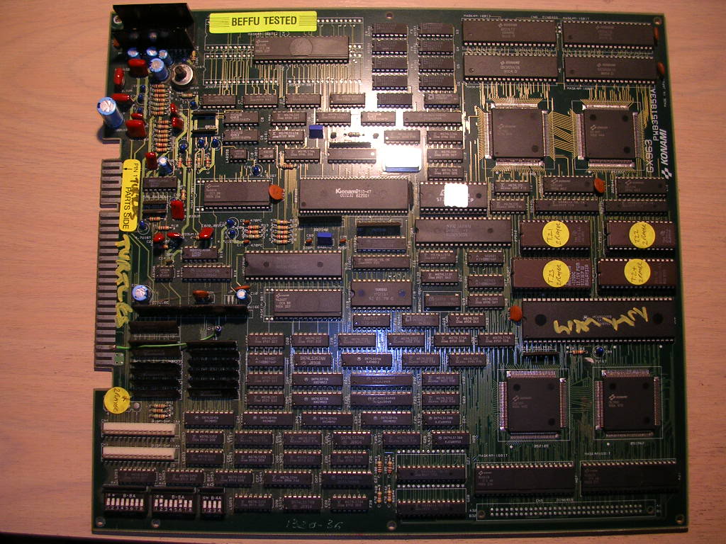
...the seller had bought it as a faulty board but had never got round to looking at it.
The board was totally untouched, beyond the fact the EPROMs had been swapped to change the game version. There wasnt a non-original solder joint on the board, but it was stone dead. My work bench had been offline for a while so I had tested it in my JAMMA cabinet, and it was very dead, not even a pop from the speaker on power up just a blank screen.
Once I got it on the bench I fired it up again and got the same result. Measuring the voltages at the board showed I had 0v on the 12V line and 0.2v on the 5V line.
The edge connector was clean enough so the only likely reason for this was that something on the board was shorting out the PSU. My old arcade PSU which crapped out on me a while back used to make a ticking noise when it was shorted by a bad board, this one it seems doesnt give any signs at all.
I gave the board a once over eyeball check looking for twisted caps or bent pins making contact and found nothing so it was time to divide and conquer.
TMNT only uses +5v and+ 12v and a short on either one could shut the entire PSU down. So I unplugged the 12V feed from the PSU and powered it back up, the board leapt into life!
So only the 12V rail was shorted, the 12v doesnt go to many place on this board and the most likely candidate for the fault was the 1000uf 16v decoupling cap at C20 that sits between the 12v and ground.
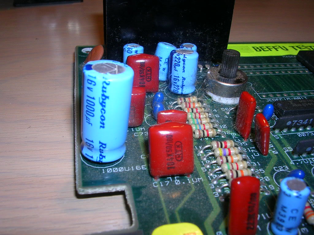
It's tall, thin and sticks up well above the other components so it is often knocked off, or damaged. This one looked fine physically and the legs were not loose inside, but the resistance measurements between the 12V and ground JAMMA pins went crazy when it was touched. Surprisingly its ESR was fine, however an ESR meter doesn't actually measure resistance to come to up with the reading, it measures a harmonic ringing effect which it then bases a calculation on to get the ESR value; in this case the cap was totally hosed.
So it came off the board...
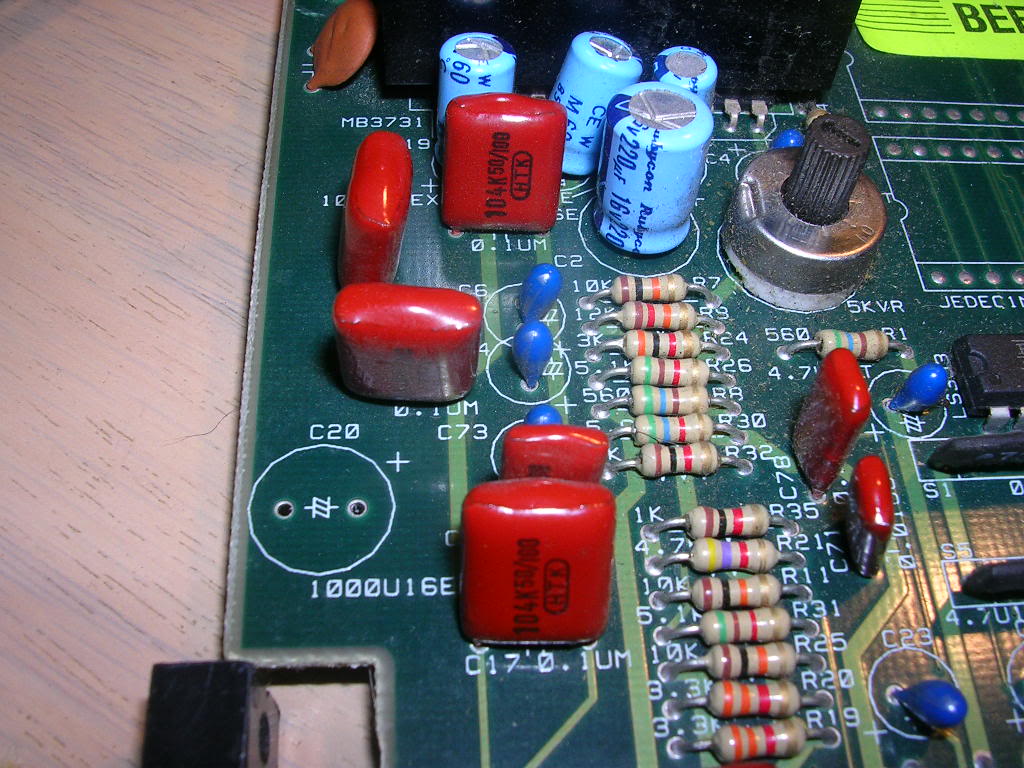
...and a replacement salvaged this morning from a scrapped chassis was ESR tested and installed.
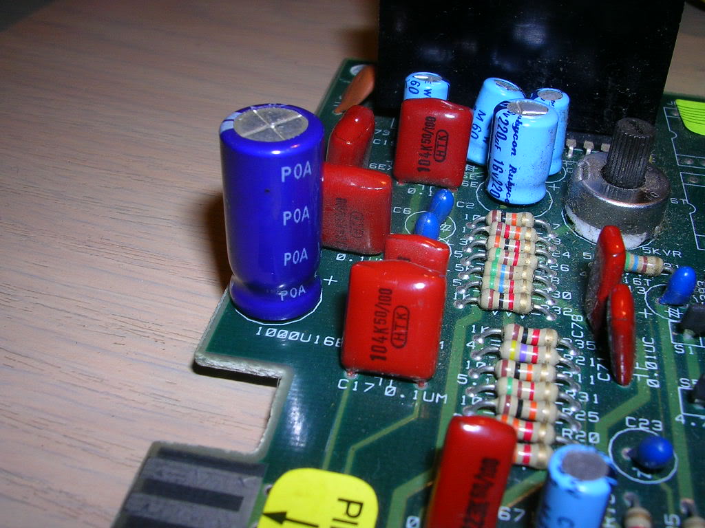
The game now runs fine with sound, amazingly (for a PCB loaded with Fujitsu TTLs and old mask ROMS) there were no other faults at all. I ran the in-depth RAM/ROM check, it passed and the game runs perfectly.
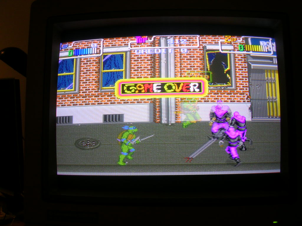
Result - took me ten times longer to write this up and upload the photos than it did to fix it
Repairer: outzone
Forum Thread: TMNT PCB Repair
Hi there I have been most stimulated by wombles posts in this section and thought i would try repairing a board, i trawled through ebay and chose a tmnt purely because of the information supplied by Womble. It cost me 20 bucks and 30 for postage so 50 bucks in total, recieved it in 5 days not bad for the us postal service.
This is the pic from ebay and upon noticing the ad this made me buy the board as well.
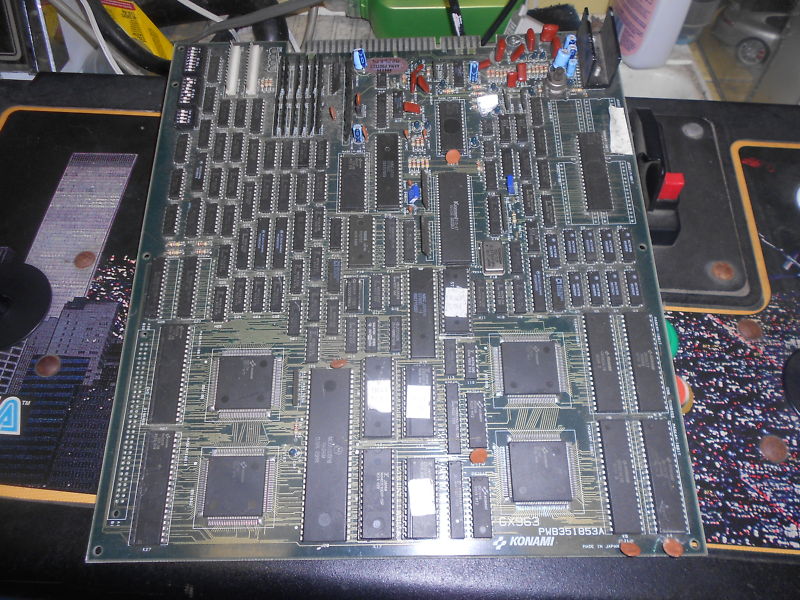
The ad said the board was not working and as you see by the picture there is a cap missing at the top right of the picture, Womble said that the cap stands Tall on the board and is usually knocked off or damaged.
I fired the board up and got a white screen which would cycle and reset to a screen of jumbled white numbers similar to rom layout but upside down, then cycle to a coloured jumbled mess then it would return to a white screen again.
Hmm...
I took the board out into the sunlight and studied all of the components, they seemed intact. There were a few scratches and bangs on a few of the chips but i could see no heat related damage so i reseated the roms and saw that one of the mask roms had been badly whacked at one stage which you can see plainly in pic number 1 on the bottom right corner.
I then i turned my attention to the solder side.
There were a few scratches here and there but one scratch looked like an impact because i could see the copper track instead of the green protective coating. Because these boards have minute tracks i got out the magnifying glass and had a closer look. I couldnt see a cut on the track in question with the naked eye but the multimeter confirmed to me a clean break on one of the tracks. On flipping the board over it was directly underneath one of the 4 square chips with millions of legs on them, so unless i traced the legs as i didnt have a shematic handy(didnt wanna kick my son off the computer either he was doing his homework) i decided rather than putting an ugly looking wire jump on the board i would try and solder a link over the track and bridge the scratch that way ot is unseen when the board is mounted. Just to solder this one link took alot of time, My soldering iron had a fat tip so i didnt leave the tip on the board very long because i knew if i damaged the other tracks i would ruin the board totally. I also supported my soldering hand like a painter to stop me shaking the tip too much. It was hard to do and i will be buying a new station in the near future so that i can do the fine stuff, i would not recommend doing this kind of repair unless you have the proper equiptment, lesson learned there.
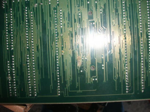
Not much of a picture i know i gotta get a new camera the link i soldered in comprised of one strand of wire coated in solder, i scratched the copper track that was broken on both sides a distance of about 2mm with the tip of my probe and lay a little solder on both sides, then layed the thin wire exactly on the track and genly applied enough heat for the wire to grab solid. i then layed the other end of the bridge wire on the other side of the track and trimmed it to the right length using a razor blade, bent it to the right shape on the board and carefully applied heat until it stuck on the track. Out came the meter and it came back wrong, i desoldered one side and tried again. This time upon checking the track was fused good and none of the other tracks in the vicinity were in conflict either. so i powered up the board.
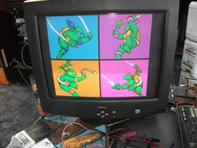
It fired up perfectly. I switche dip 8 and the sound came through faultlessly. This repair took roughly one and a half hours, its an easy one but i am wrapped. Thanks to Womble for motivating me, Its going to be a hard road i know but i was so happy i had a win its motivated me even more.
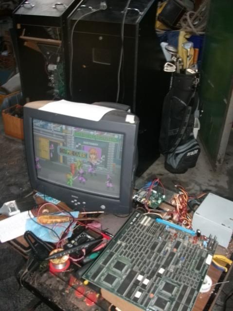
Teenage mutant ninja turtles that attract is so kool. My son is on me to mount it in a cab now lol.
Kind regards Ray
