PCB Repair Logs Chase HQ
Chase HQ
 |
|
| Manufacturer | Taito |
|---|---|
| Year | 1988 |
| PCB Image | Chase HQ PCB |
| Pin Out | Reserved |
Repairer: Womble
Forum Thread: Chase HQ PCB Repair
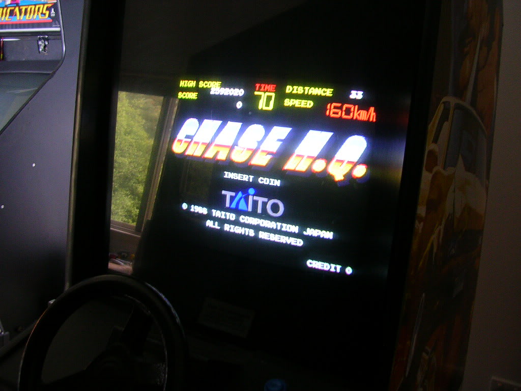
Something is in the air I think, have had a week of things going wrong, firstly the PVR shat itself, then the vacuum cleaner packed up, and to top it off my Chase HQ cab died! My wifes best friend has a couple of kids and they were over the day after I got the cab, the little boy was very keen to play it but at that stage I hadnt fixed the steering. The next time they were over I fired up the cab only to be greeted with this...
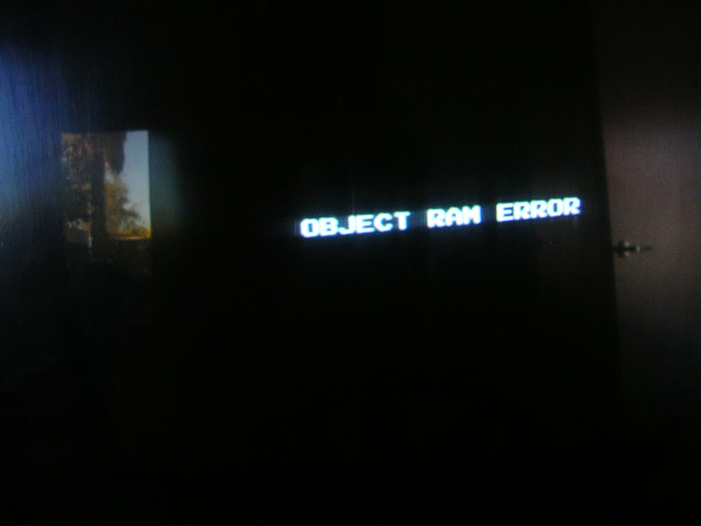
...Object RAM Error - brilliant! So he didn't get to play it that day either. I set the dip-switch 3 on dip bank A to on as this selects the diagnostic mode in the hope of more specific tests but it didn't have any effect, the board just cycled giving the same error, time to whip it out of the cabinet.
This board isn't quite JAMMA, it applies the power in the same way as a JAMMA edge connector so you wont wreck the board if you plug it into a JAMMA harness, but you wont get any video as that leaves the board through another connector, but it meant I could easily power it up on the test bench and have it running blind for some oscilloscope action.
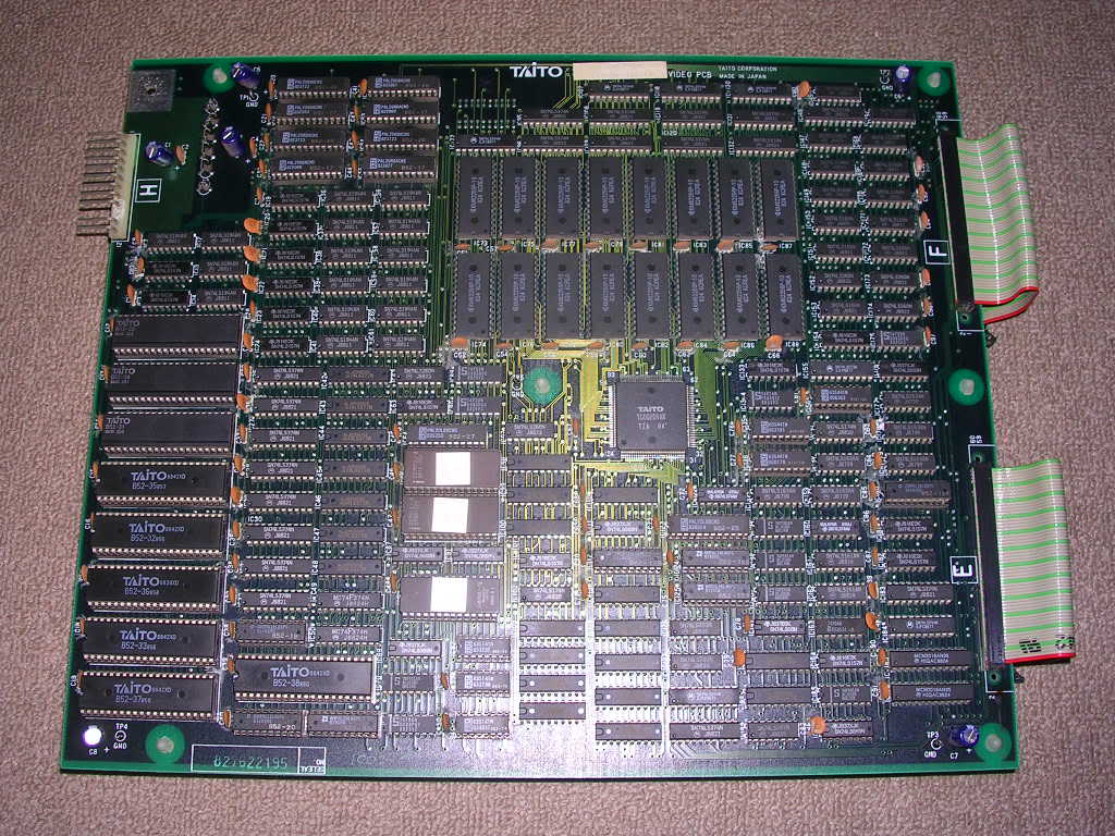
Chase HQ is a two board stack and it has RAM scattered all over the place so the first thing was to track down which chips were the object RAM.
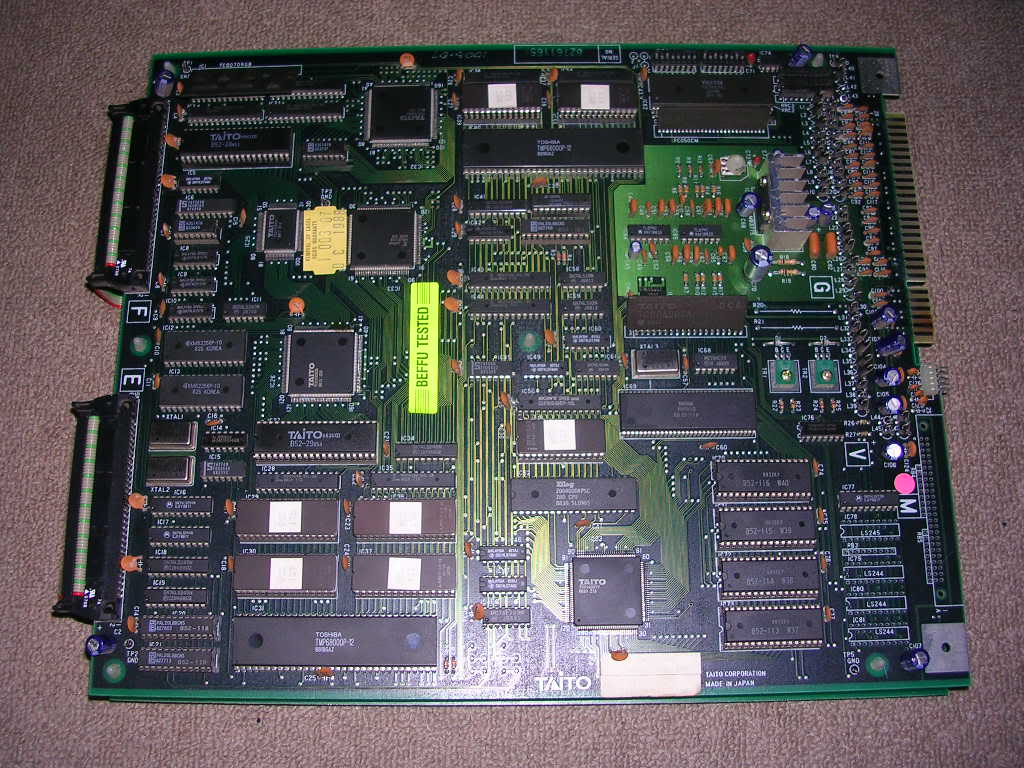
Thankfully the schematics are available and they are a scan of one someone has added some handwritten notes to, so all the RAM on the CPU board has been worked out by whoever annotated the original. The video board had no annotations on its schematics but there are only two RAM chips on that board which is where the object RAM is likely to live. Also the buses going to these chips were called OBA and OBD, for Object Bus Address and Object Bus Data. By the fact that the OBD bus had 16 lines I knew that these chips were acting as an active pair with one providing the Hi byte and one providing the Lo byte for the 16 bit word.
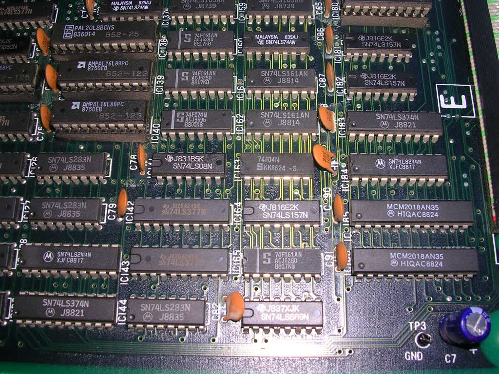
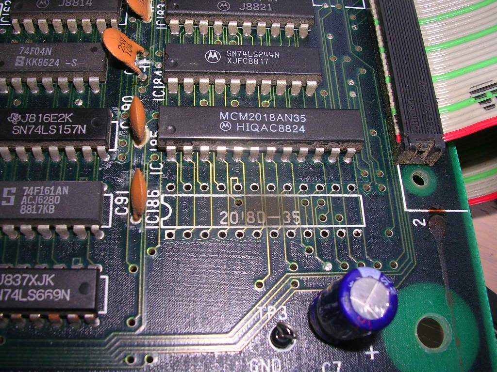
So the Object RAM lives at IC185 and IC186 which are MCM2108AN35 chips, basically 35nsec 6116 type SRAMs...
...that live in the bottom right hand corner of the video PCB
Poking the scope at them I could see when the board was reseting, running the test, then pausing while it showed the error on the screen, then resetting and repeating. The address bus on both chips was active, the /WR and /OE pins were doing what they should, but only IC185 ever showed any activity on its data lines. The chip at IC186's outputs were floating, it doing a very good impression of a chip whose /CS or /OE pins are held high. The /OE pin is used to silence the chips outputs if it shares the bus with another chip where only one chip should have control of that bus. The /CS pin puts the chip in a low power standby mode if it is held high, but on this board the /CS and /OE pins were tied to ground so IC186 was shot.
So it was de-soldered...
... and a TMM2018-35 from a rust bucket Midnight Resistance PCB soldered in its place.
Even though I had no monitor connected I could tell from the scope that this had changed something. What I was expecting to see was both chips light up on the data bus and to see the whole board busily active. What I got was peace and quite, both object RAM chips were doing nothing, but the board was no longer resetting. Puzzled I put it back into the cabinet so I could see the output, when powered on I was greeted with the diagnostic menu asking me to use the steering wheel to select either steering or PCB diagnostics. This explained why the object RAM was doing nothing, it was a static text screen wait for an input I could not give it outside of the cabinet.
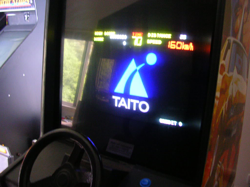
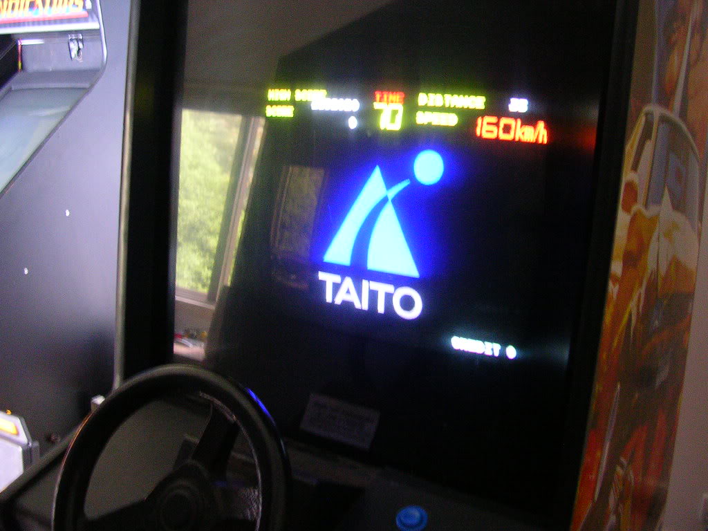
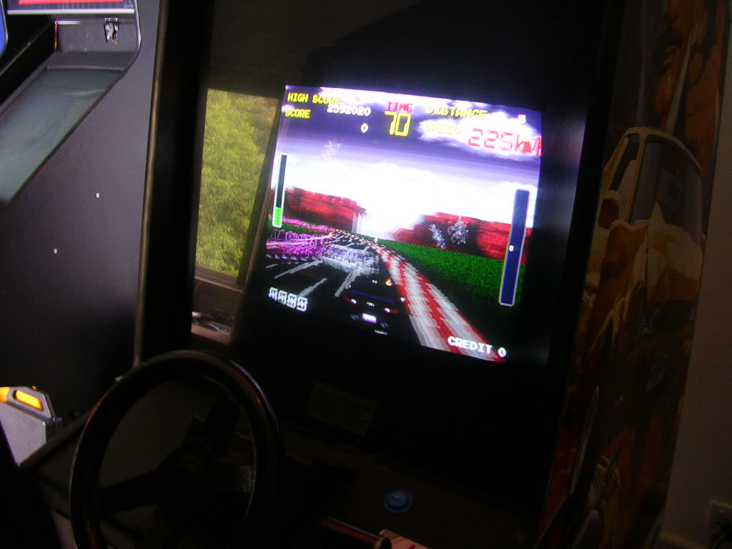
So I flipped the dip-switch back to game mode and powered it up.
Error messages stating specific RAM or ROM faults shouldnt be taken literally, the board has no way of knowing if the RAM or ROM is back, all it can say is that it tried to read from a ROM and didnt get the data it was expecting, or in the case of RAM that it wrote a test pattern of data to an address(es) and then tried to read it back and got something different. Of course it could be the ROM or the RAM as was the case he, but in many cases it is a logic fault in the section of the PCB that controls those ROM/RAM chips, or a problem on the data or address buses.
Anyway - Mr Driver is back, he says we have to go, plus Nancy is in a flap about something again
