PCB Pinouts Konami Classic
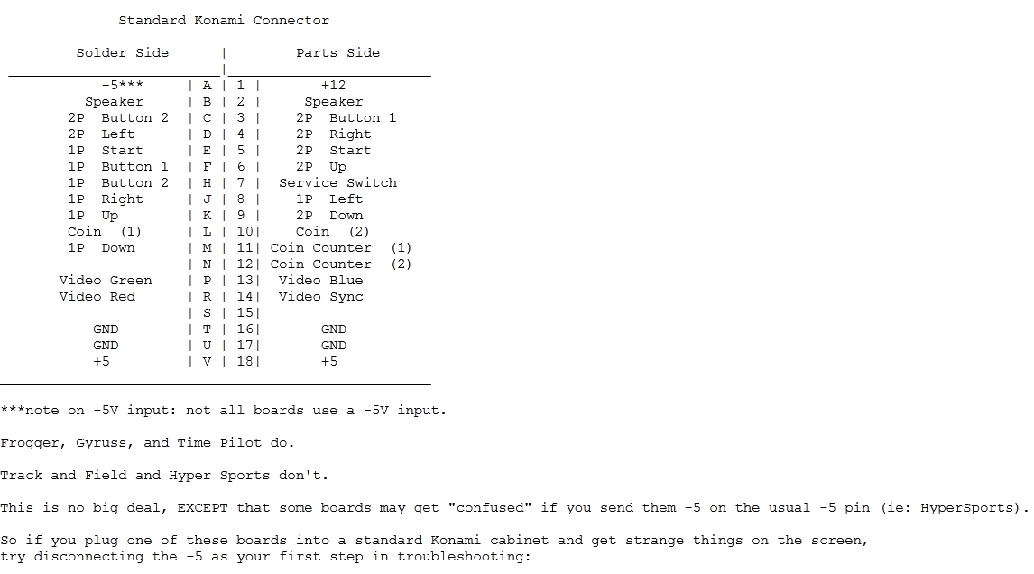
fdgsdg dsfg sdfg sdfg sfdg fsdg sd fgsdfg IMPORTANT: DO NOT WIRE THE VIDEO GROUND TO THE HARNESS OR POWER SUPPLY! THISNEEDS TO STAY ISOLATED.PARTS (TOP) SIDE | SOLDER (BOTTOM) SIDE+12V 1 | A -5VSPEAKER * 2 | B SPEAKER *PLAYER 2 BUTTON 1 3 | C PLAYER 2 BUTTON 2PLAYER 2 RIGHT 4 | D PLAYER 2 LEFTPLAYER 2 START 5 | E PLAYER 1 STARTPLAYER 2 UP 6 | F PLAYER 1 BUTTON 1SERVICE SWITCH 7 | G PLAYER 1 BUTTON 2PLAYER 1 LEFT 8 | H PLAYER 1 RIGHTPLAYER 2 DOWN 9 | I PLAYER 1 UPCOIN SWITCH 2 10| J COIN SWITCH 1COIN COUNTER 1 11| K PLAYER 1 DOWNCOIN COUNTER 2 12| L PLAYER 1 BUTTON 3 **VIDEO BLUE 13| M VIDEO GREENVIDEO SYNC 14| N VIDEO REDPLAYER 2 BUTTON 3** 15| O (UNUSED)GND 16| P GNDGND 17| Q GND+5V 18| R +5VPARTS (TOP) SIDE | SOLDER (BOTTOM) SIDE* positive terminal on top, negative terminal on bottom** the third button is only used on certain games - there is no standard for it
