PCB Repair Logs Snow Bros
Snow Bros
 |
|
| PCB Image | Reserved |
|---|---|
| Pin Out | Reserved |
Repairer: Womble
Forum Thread: Snow Bros PCB Repair
Picked up a couple of faulty Snow Bros boards a while ago.
One had missing chips so I focused on the complete one initially, the seller had sold them both as having gfx issues and stated that neither had been hacked around, not quite sure what he calls the fact of logic chip hacked off the second board, old age probably.
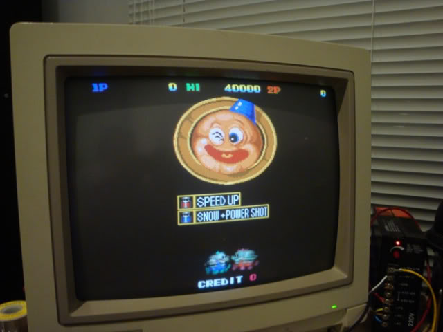
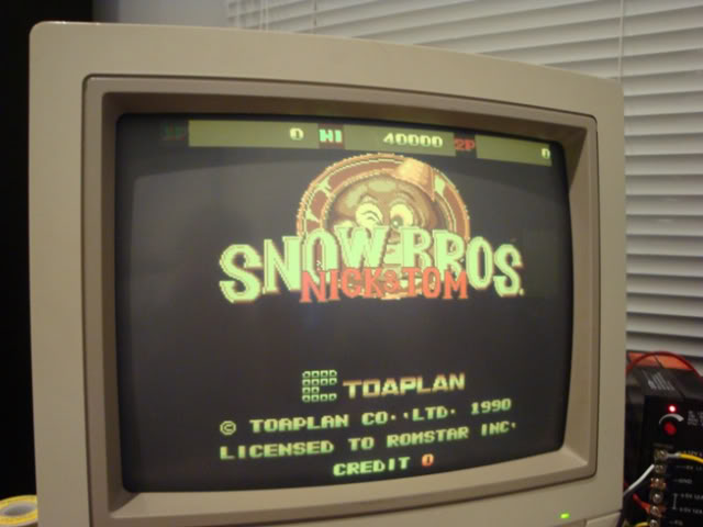
Anyway - the fault on the 1st board was that the colours were messed up and the screen was very very flickery.
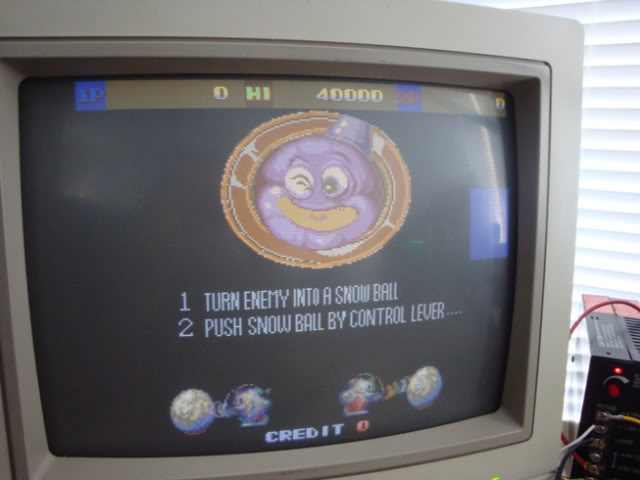
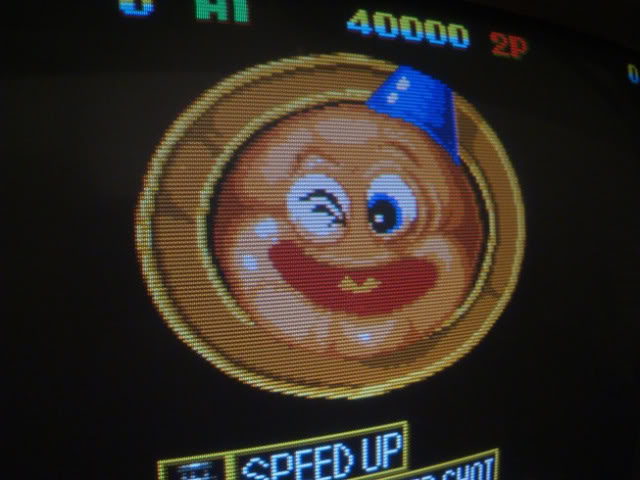
Hard to catch "flicker on photos" but you can see the raster scanning down the face changing the colour from blue to pink, thats flicker!
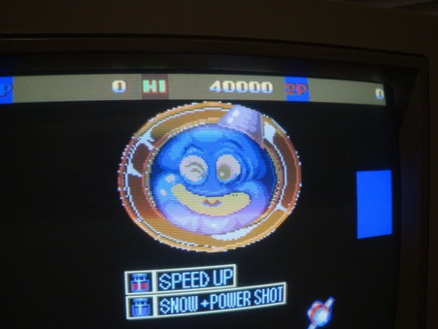
The game looks ok but the colours are washed out and that damn flickering....
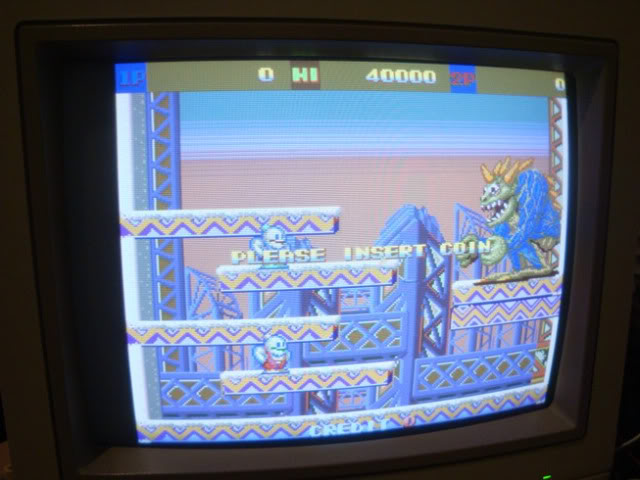
I went over the board looking for damage and found nothing, despite the dust it is a very nice board. The game was running fine and the sounds were good so I didn't bother to dump the 4 ROMs, just reseated them.
Had a poke around the board with the scope and found that the majority of the chips had what looked like an unstable logic 1 state - the high logic level was pulsing in time with the screen flickering, by looking away from the screens but watching the monitor and the scope screen out of the corner of my eyeI could see that the images were exactly in time with each other.
At that point I thought it would be an easy fix, all I had to do was find the chip with normal inputs and bouncy outputs and that should be the problem - nice idea except I couldn’t find a chip like that. I was somewhat concerned by the NEC D41101C chip by the custom IC, I struggled to find out what it was. It looked rather like a SRAM chip and if I assumed the pinout was the fairly standard SRAM pinout then it did have a few outputs bouncing around, however it also had an "address pin" that looked exactly like a clock signal which kinda buggered my theory. Turns out it is something to do with the video, a "910*8 NTSC line buffer", either way when I had the correct pinout it was clear that its outputs were ok, it was the input signals that were bouncy and that clock signal was indeed a clock signal.
I really dislike having a board that is doing bad things when there is a fat custom chip present, this one is a 120pin surface mount chip that I couldn’t find any info on. Thankfully customs are pretty robust so I left it alone and hoped it was not the culprit. Thats about all you can do with customs, leave them alone and look for other issues, if you find none then you end up back at the custom again.
Poking around the two Sharp LH5126-12 chips at 6N and 7N I found what looked like a fault but turns out to be totally normal. Address pins A8, A9 and A10, along with data pin D7 were all tied low. This is very unusual as it effectively removes a large lump of the RAM space and partially buggers the output. The other RAMs at H6 and H7 are used normally.
Sticking with the RAM I hit the 4 DRAM chips at A2, B2, A4, B4 - the 1st arcade board I have seen with DRAM instead of SRAM. It needs more support circuitry but the capacity is a lot higher, probably why DRAM has since taken over as the standard RAM chippery.
At this point I made a stupid mistake, arcade boards usually have the chips lined up so that when the JAMMA connector is on the left hand edge (how my bench is set up) the chip markings are the right way up, this board is the reverse. I read the chips as being 4164 chips - very very common chips from the early to mid 80s, so I pulled out the pinouts for them and went round the chip. It didn’t make much sense, pin 1 on 4164s are not used, yet pin one on these chips was happily active. For some reason this didn’t ring alarm bells, and as I have a nasty habit of counting up from 1 to find a pin on side A and down from the 5V pin to find a pin on side B I also did not spot that 4164s have 16 pins and these buggers had 18. 4164s are 1 bit wide chips, each address location is only 1 bit, so they are usually used in banks of 8, each chip contributing 1 bit to the byte being read.
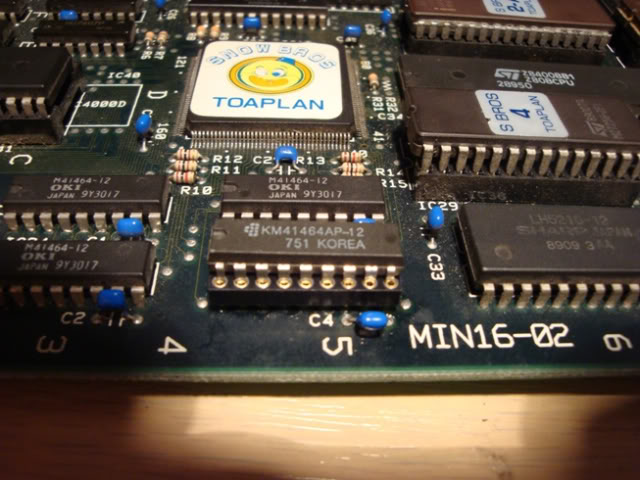
These chips were actually 41464s a very different animal, an easy mistake when reading upside down at an angle I guess. These chips are more modern than the 4164s, slightly more inline with the vintage of the board actually. They are 4 bit wide chips, ie 4 data output pins rather than the single one on a 4164.
Once I actually applied the correct pinout to the chip I was trying to troubleshoot on the scope it made a whole lot more sense. Hitting the 4 data lines on all four chips I found one chip that had very unhappy looking outputs. Because of the flickering it was hard to get a good zoomed in view of the data lines, on the good chips with the best scope settings I could find, the data line is frenetically busy,
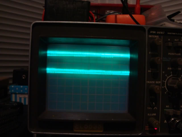
... on the suspect chip it was very quiet, a lot of bumping as per all the other chips, but not much activity.
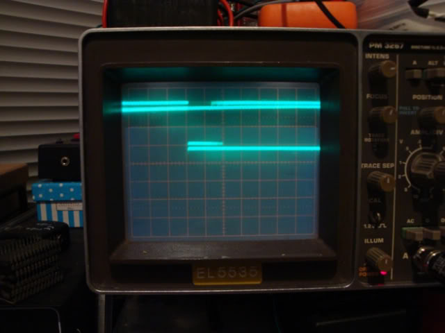
So I desoldered that chip and powered the board back up without it.
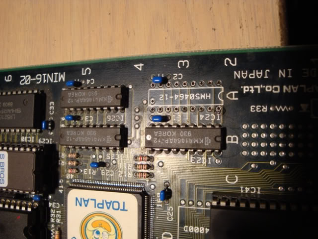
Nothing changed, the bouncing was still there, the colours were not great and the screen was flickery, this was good news. If the chip was doing something then the board should behave differently when it was physically removed. This suggested that the crap colours and flickering are what the board does when one RAM chip is missing, either physically missing, or still there but knackered.
Found a guy on eBay in the US who happened to be selling 4 of these chips at $2 each, so I bought the lot, soldered in a socket and waited for the parcel. It arrived today and when I dropped in a new chip the problem....
The bouncing logic issues have gone away too, I can only guess the board strobes through each chip in turn and the lack of a working chip at that location causes major instability, am surprised that it affects most of the board though, it can't be a short in the chip from the CAS or RAS signal as the instability was there when the chip wasn't
Just got to fix the second one now, handy that it is almost the same fault
Repairer: Womble
Forum Thread: Snow Bros PCB Repair
Thanks, am looking fwd to a good blast on it - my wife loves games like this too.
Decided to have a go at the second board and it wasn't quite the same issue, will post it as a reply to this thread as there is a limit to the number of photos you can have in one post.
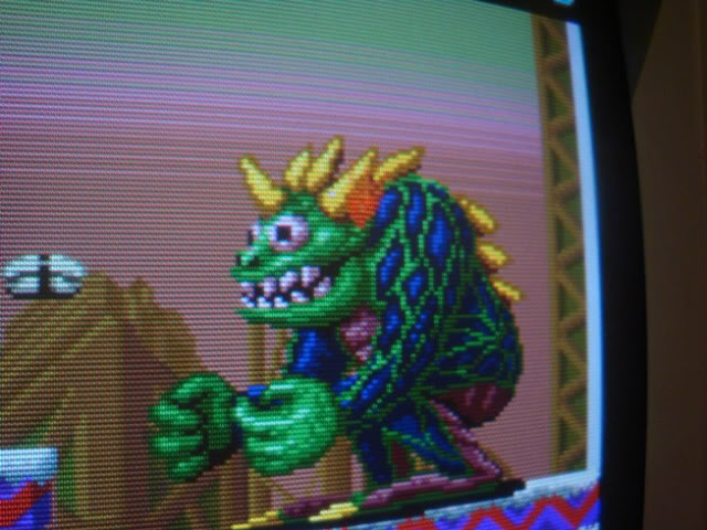
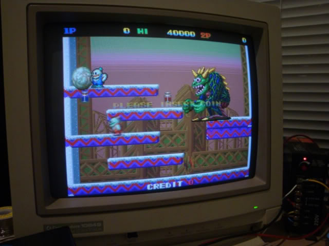
So - the second board also had "gfx issues", when it 1st arrived and I plugged in it did this - the game ran but everything was red and flickering like mad.
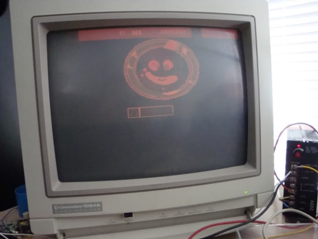
The RGB lines connect back to 3 resistor networks strung across two 74HC273s, at 9N and 9M, one of which had been removed rather violently by a previous owner so no surprise the colours were borked. Despite the way it looks all the plate-through holes were thankfully still connected to their tracks. The chips ground pin was still in its hole and had been cut off the chip when they gave up on it. This board is a pain to work on, the copper ground and 5V plane must be massive compared to my other SB board, its almost impossible to get things off this one.
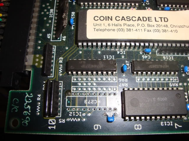
The existing HC273 tested as OK but I fitted a matching pair of new chips and brought a bit more life back to the board, a nice sepia tone to it all, plus flickering.
Hitting the output pins on the 41464 chips as per the 1st board I found the chip at 4A had all 4 outputs stuck wobbling around high, so whipped it out, fitted a socket and a new chip.
I was expecting the board to fire up perfectly, except it didn't. The flickering was gone but everything was still sepia, a distinct lack of blue!
I put the scope on the blue jamma pin and got nothing, the red and green were happily buzzing away. The blue pad on the JAMMA connector connects straight to the far end pin on resistor network RA5 at 10N which connects to the HC273s. On closer inspection it looks like this has had a bit of a whack. There was a small crack in the black housing by the +5V bus pin, which when poked with a screwdriver, flaked off.
I desoldered the whole thing and the bus pin (that connects to 5V) fell off. I went over my scrap boards and could not find another one that was the right number of pins and the right rating, nor could I actually confirm anywhere that this is a normal resistor network - am not sure it is based on how it is connected in this circuit, so I got my mini files out and attempted to mend it. I filed just enough of the black coating to expose some of the metal pad on the internal structure. Refitted the component to the board minus the bus pin, then took an ofcut from an LED leg and bent it through the PCB hole so it lined up flush with the exposed inner metal on RA5. Soldered the old LED leg to the PCB then soldered the end to the broken edge of RA5.
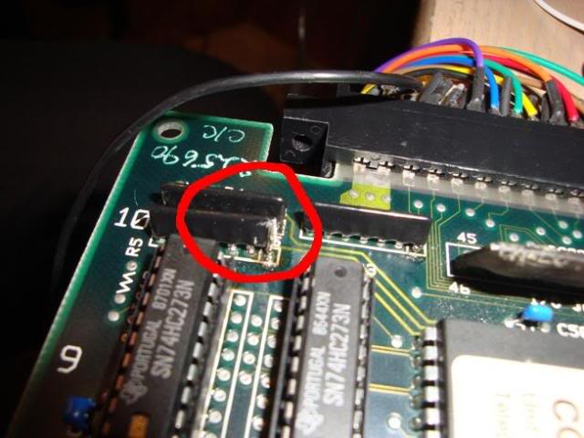
A quick trim with the wire cutters and powered her back up.
We have blue!!
In fact we have a perfect Snow Bros board
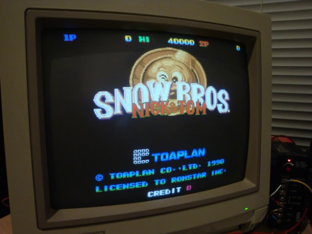
I put a drop of PCB lacquer over the repaired RA5 to prevent it from oxidising as there was only a tiny bit of metal to work with originally, I won't be lucky again
