PCB Repair Logs Cadash
Cadash
 |
|
| Manufacturer | Taito |
|---|---|
| Year | 1989 |
| PCB Image | Reserved |
| Pin Out | Jamma Pinout |
Repairer: Womble
Forum Thread: Cadash PCB Repair
Bought this board recently, primarily because I knew it still had its TC0070RGB SIP that was damaged on my Rainbow Islands board (I patched that one up but eventually plan to replace it with a mint one).
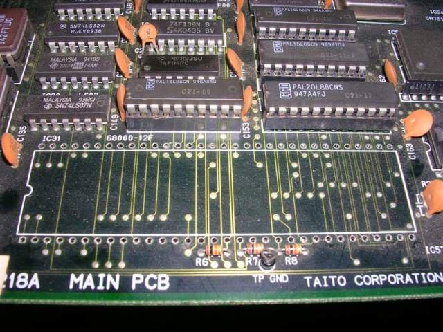
When I got the Cadash board it just looked too good to treat as a donor board so as happens to a lot of my scrap boards, I decided to have a go at fixing it. Only 2 obvious issues with the board, firstly the CPU had been desoldered (thankfully very neatly),
and secondly a 1000uF electrolytic had been bashed out of the amp section.
The solder on the cap legs looked like it had been a dry joint from new and as the cap is quite tall it had just pulled free.
Fixing both issues was easy, thankfully the previous owner had not soldered the CPU back in, just put it back on the board and folded over the pins at each corner to hold it in place. This saved me from de soldering it again to fit a socket if I was going to have to get the Fluke 9010 onto it.
The bashed cap ended up in the bin as its ESR was 7.4Ohms, a 16V 1000uF cap should be around 0.1 Ohms, the physical abuse it got probably damaged the rubber seal at the bottom. I had to resort to drilling out one of the solder hole though as the sheer amount of copper in the area meant I could not clear the hole even after flooding it with fresh solder.
This is a pretty dangerous move as I needed to retain the plate through hole (ie the metal tube running through the board), but as the smallest drill bit I had went through the easily cleared hole on the right I thought it would probably work seeing as solder is quite soft.
Hole intact
As I have bad habit of dragging home any smashed circuitry I find while walking the dog (have got lots of spares I have actually used on boards that way) I happened to have a 1000uF 16V handy, and could verify that its capacitance and ESR were fine. There's intrinsically nothing wrong with using old caps as long as you can actually test that they are ok, just because they are old doesn't mean they are bad or just about to fail, in fact you could look as it from the angle that if the cap is years old and still has perfect ESR its probably not a fragile one.
Anyway - fixed the cap, and fitted a 64 pin socket for the 68000 CPU, slapped in a CPU and fired it up. I had tested the CPU that came with the board in my Moonwalker board and it worked fine, and as it was still in that board I pulled another 10Mhz 68000 from my stock and dropped it in.
On power up the board did this...
...nice useful messaege "WORK RAM ERROR", except I had no idea where the Work RAM actually was on the board, only that it was mostly likely to be fairly close to the CPU. The closest was a block of 4 TMM2063 SRAM chips, a sort I have seen fail before.
Poking the other SRAM chips dotted around the board showed most were in standby anyway, not uncommon at such an early stage of bootup.
Pointing the scope at the 4 chips I found that the pair closest the edge of the board had unhappy looking data pins, D7 in particular looked very weak...
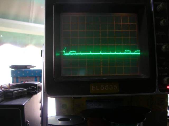
...compared to D6....
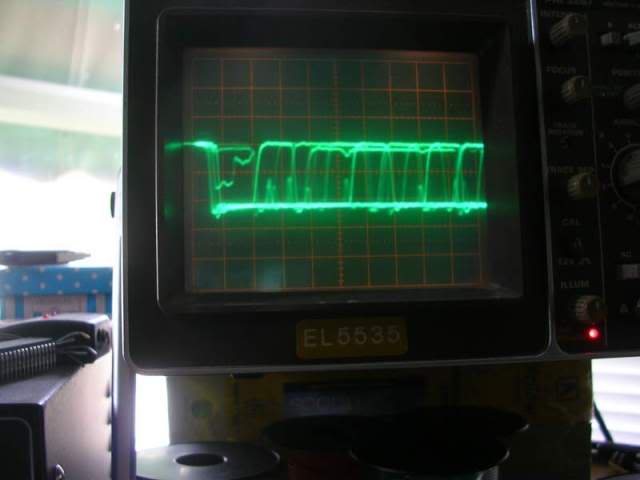
..which also didn't look great, but the D7 output was so weak it was never getting anywhere near the voltage needed for a logic 1, at least D6 was covering the right range.
While I was poking around things suddenly got worse, the useful error vanished and I got this.
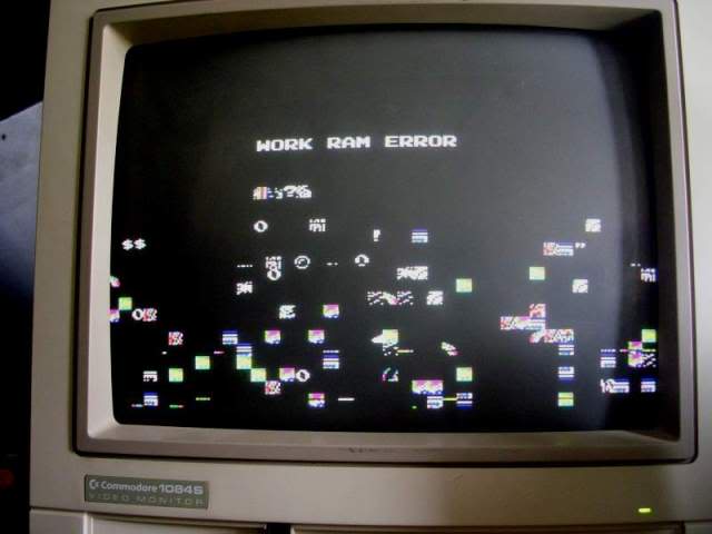
Seeing as things got worse while I was probing around the two chips I already suspected I took it as a sign I was on the right track, something had just died a bit more.
Judging by the way the traces ran these chips were probably strung across the same 8 data bus tracks and the 16 address bus tracks therefore both chips were suspects so I took them off the board.
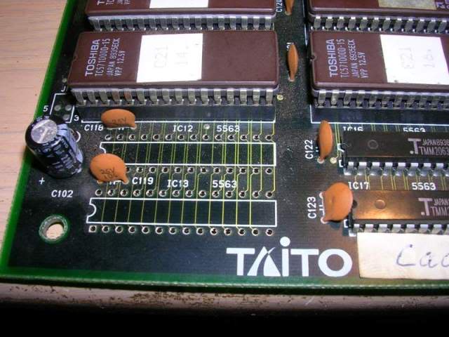
I desoldered both chips and put them through my Eprom tester's SRAM test, the inner of the two chips passed the test happily but the outer of the pair failed with an "out of spec pin" on the OE leg, which might well explain why both chips looked crappy, the board could not isolate one chip of the pair so both were talking on the bus and fighting each others signals. So fitted some sockets, put the good one back and slapped in a Sony CXK5864 in the second socket. Connected it all up and flipped the switch...
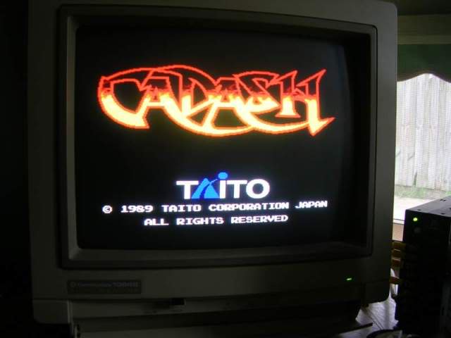
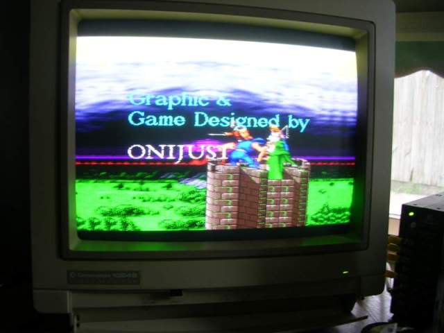
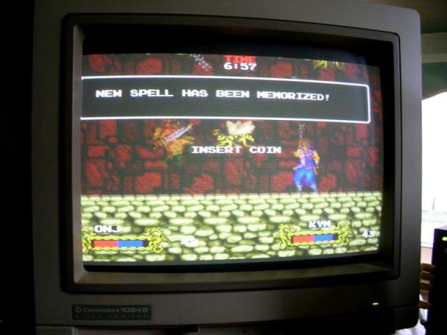
... fixed, stunning graphics in this game too!!!
I decided to reunite the original CPU with the board but whenever the old CPU was installed the game would not boot, blank screen and angry buzzing noise was all I got. It was a 10Mhz 68000 and the one I had used throughout the repair was also a 10Mhz 68000, but as the old CPU worked fine in Moonwalker I went and looked at the MAME source and found that the game actually needs a 12Mhz CPU. So the chip that came with it clearly was not the original CPU. I can only guess that the board developed its RAM fault and then the CPU was harvested as spares.
I was just lucky that the 10Mhz one I used was happy being overclocked, the one that came with the board aint happy at 12Mhz at all, will try and track down the right speed for it, my stash contains only 8Mhz and 10MHz chips.
One happy board tho!