PCB Repair Logs Pong
Pong
| File:Marquee pong.jpg | |
| PCB Image | Pong PCB |
|---|---|
| Pin Out | Reserved |
Repairer: hal9000
Forum Thread: Pong (Syzygy) PCB Repair
hi all..
I decided to deviate from my recent Lasergame obsession and jump back into one of my other passions for personally collecting arcade games... Its nice to wander off from my everyday slog of fixing BORING normal video arcade games from the early 80's.. YAWN.
So i found one of my Syzygy Pong pcbs kicking around in a box in my loft, and decided i should finally get to looking at it. Its a good condition 'E' revision pcb, with a laid-flat filter cap arrangement.
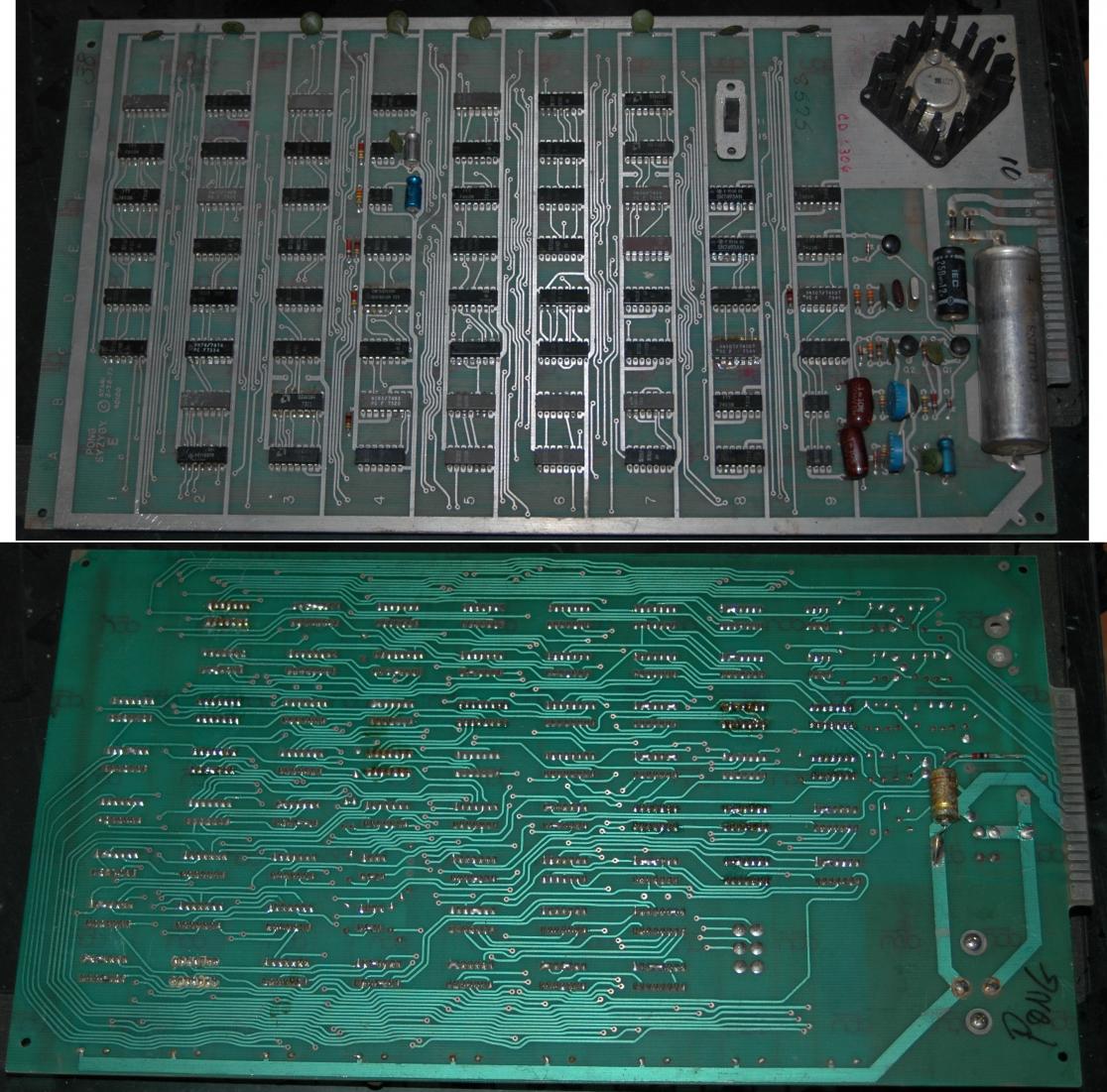
PONG schematics can be found HERE there isn't a good copy out there, they all suck. I have paper originals and they are the same crappy quality.
And here is what i found:
1) First powered it up, stone dead, no video output.
2) Pin 11 E6 showed a good waveform on the scope, so the xtal must be good.
3) Pin 3 F6 was good, so the rate divider (flip-flop cuts speed in half) was good.
4) Pin 11 F8 (7493 - Horizontal sync chain) output was stuck low, this feeds the clock input to the next one in the line, so i replaced it.
5) Still didn't see any ouptut from F6 (7474) Pin 5+6 or from pin 8+9 despite good looking inputs, so replaced E7 and the pcb sprung into life - of sorts, the image was not stable, waveform outputs from E8 (7493 - Vertical Sync chain) were being miscounted and were not transitioning all the time between the TTL thresholds. I replaced E8 and i got a stable picture!
6) The game image now looked like this :
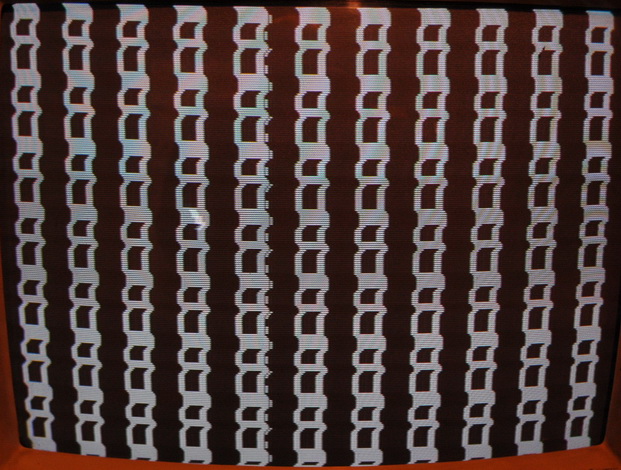
So - the ball is bouncing around the screen, bouncing off of all the edges as it should in attract mode. The net is there, but the Score digits fill the entire screen.
I went straight for the Score circuit, looking for the SCORE signal, it was too busy, ie, it was on most of the time. Working backwards through the gates i notice they all had too much juice on them, the score is only supposed to occupy the top 40 scanlines or so, so every signal you should see should be silent for most of the raster. These were just on all the time. Anyway, after getting lost in the schematics i ended up at C5, which is a BCD to 7-segment LED display driver IC, this has actually been repurposed to generate the scores for Pong. Looking HERE i found the pinout (it was not in my TLL data book!) and i could see that the output from pins 9-14 were all just jammed at 5v, meaning they were switched on the whole time. I grounded pin 4 and found the outputs didn't change at all, so i knew right away this chip was duff. I removed it, and replaced it (with an LS - all i had) and bingo, i got a good game screen with scores!
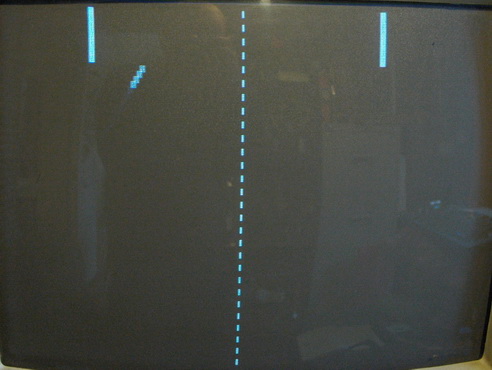
7) So, the game looks good in attract mode now, but when you put a coin in, the screen just flicks, the paddles do not appear, and the ball does not dissapear and get auto-served. Anyway.. I got a bit lost and started centering on the COIN input (schematic area B6), because i didn't remember such a screen flick from previous pong repairs... I removed C8 from circuit (74107) but from a previous repair it wouldn't come out without damaging the PCB foil so i ended up having to cut it out so i just replaced it with a new one, with no difference to the coin behaviour.. I then went for the 7404 @ C9, removed it from circuit and tested it in my ABI chip tester, it was good, so i put it back in circuit, no difference.
8) So I went and had a cup of tea and a think. Most TTL games work off of simple game 'states' Pong has just two states, Attract mode and Game mode. There is no gameover, or high score entry, or 'insert more coins to continue' modes or anything complex, Pong just has two states. This way, just one signal can be used to tell the multitude of circuits what operating position they shoud be in. This magic signal is /ATRACT (active low) When its high, its in game mode, when its low, its in attrat mode. This signal connects to a lot of different IC's, it resets and starts the score counters, the serve timer, the sound circuits, the paddle circuits, ball bounce and rate circuits, sound enable etc... So, I should have looked at this first, because it was now obvious that the game wasn't actually starting when coined and the chips surrounding the coin input appeared good. I went straight for the /ATRACT signal this time, finding it on the schems (near area B/C4) output from the 7402 @ D2 pin 1. Now when I coined the game and looked at the input pins 2 and 3, i saw a change of state (i forget which/how) but the output pin 1 remained low at all times. So i whipped out D2 and replaced it...
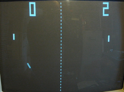
9) Result! the game now goes into 'game' mode, the paddles appear, the ball auto-serves from the net, and the scores reset to zero and count up to 11 before the game goes into attract mdoe again. Problem is, there is a buzzing tone noise the whole time, it sounded like a proper game noise that was just stuck on. I went to the sound output section on the schems (area C5) and found the 7410@C4 has three inputs, pin 4 just had a square wave on it the whole time, tracing back through C3 (7400) i find that the output from C2 pin 6 was sitting at about 1.5v (HIT SOUND) instead of actuating when hits were being made. It had good inputs at pins 1 (HIT) and pin 3 (clock), and piggybacking a good 7474 on top shut the noise up. I chopped C2 out and replaced it... ahhh.. the noise was back to normal.
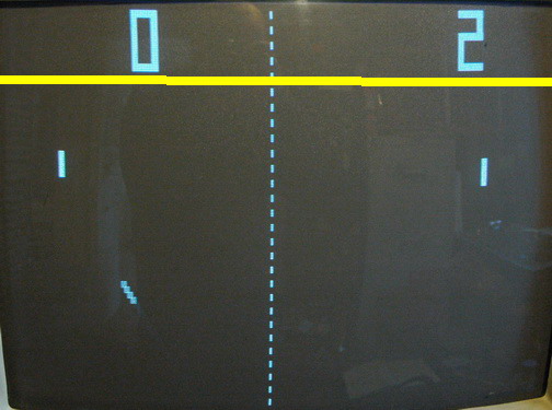
10) Only problem now is that when you move either of the paddles up the screen and get to the lower edge of where the scores sit (indicated by the yellow line on the photo above) the paddles just completely dissapear, if you descend the paddle control again, the paddle re-appears... most spooky... So i looked at the 555 timer that produces the paddle on the left of the screen, this is the 555 @ B9 (schematic area A6). On looking at pin 3 (the main output on 555's) with my scope, I could see the asynchronous square wave getting shorter (mostly remaining at 5v) when i moved the paddle control to the bottom of the screen, however, when i moved the paddle control upwards, when i reached the yellow line in the photo, the signal just went entirely low, losing any high-going square wave, it just dropped out completely. So i looked to the clocking input on Pin 2 (/256V this is the 256th division of the vertical sync signal and should be a constant square wave regardless fo what the game is doing) and noticed that this would drop to 0v when i reached the yellow line, somehow, this signal was dying when the paddle position was high up on the screen. Who knows exactly why, but this signal came from the 74107 @ D9 (schematics area D4) pin 6.. I replaced this sucker and the paddles no longer dissapeared.
End result, its now fully working!
Hope you liked the log.