PCB Repair Logs Psychic 5 Bootleg
Psychic 5 (Bootleg)
| File:Marquee psychic 5.jpg | |
| PCB Image | Reserved |
|---|---|
| Pin Out | Reserved |
Repairer: Womble
Forum Thread: Psychic 5 (Bootleg) PCB Repair
Had been chatting to DisQo for a couple of days about his Psychic5 PCB that played blind, from photos it was clearly a bootleg and there is a note on the game entry at KLOV saying that they cocked up the JAMMA connector layout when they ripped off the board and got the solder side and parts side swapped over. This would bugger up would be the video signal, the test buttons and it would reverse the player controls, 1P would be 2P and visa versa. Am not convinced reversing them would cause no video at all, as it would have 2 of the 3 colour channels and be missing sync, it wouldn't be pretty but you would see an unsync'd image surely.
Anyway there was no way to prove any of it remotely so he posted the board my way.
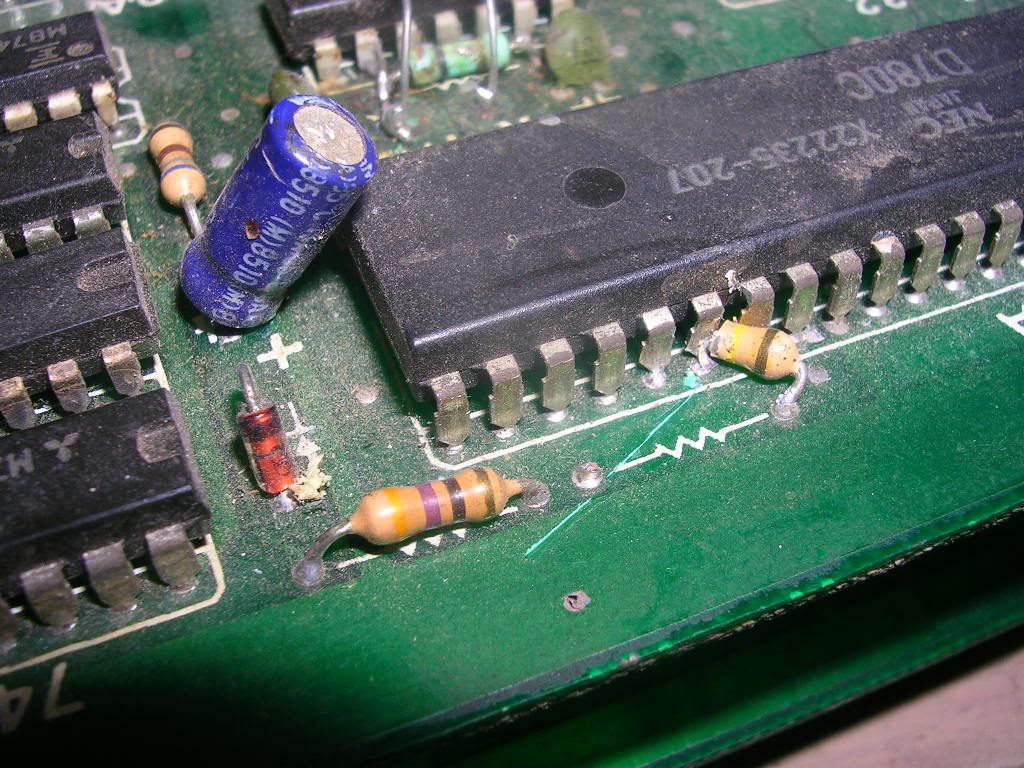
What arrived was a bootleg that had been mightily buggered around, a number of really bodgy repairs had been carried out many years ago judging by the colour of the old solder, plus there looked like damage to a resistor by the sound Z80.
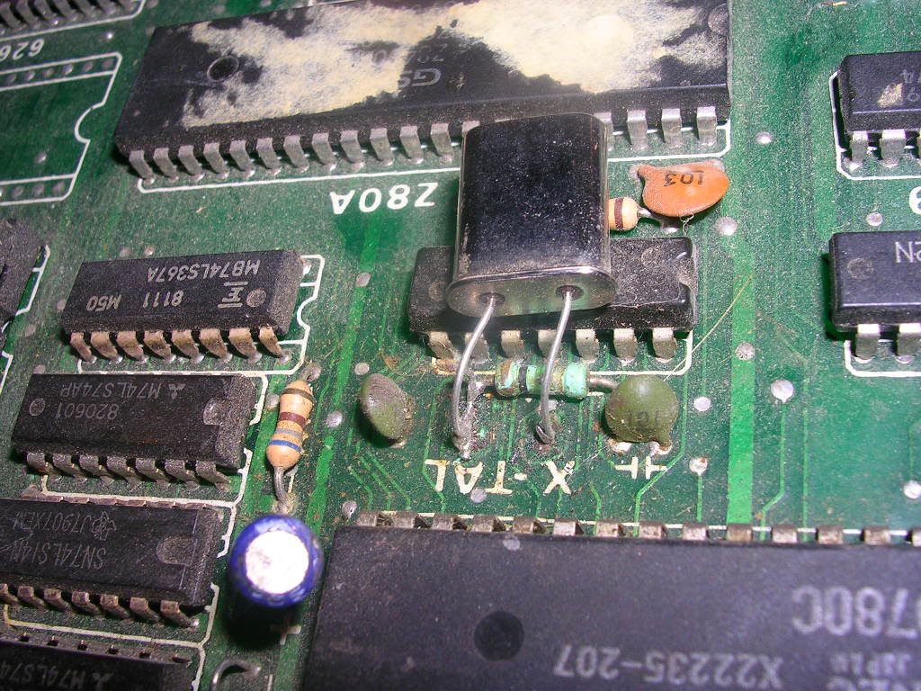
A new crystal had also been installed (badly)...
...a load of caps replaced (also badly)...
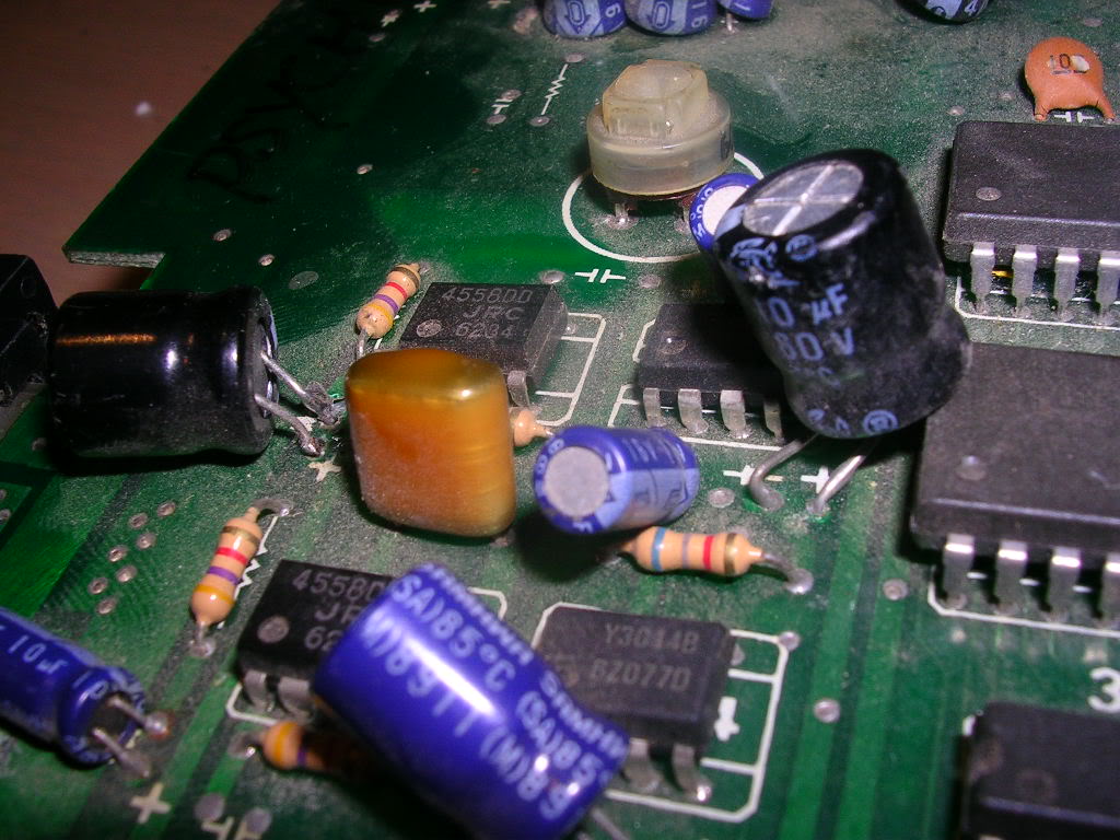
... I think someone should tell who ever did these repairs that it isn't illegal to trim component leads and that you don't have to solder them in at the end of the long legs they come with. The caps were also far too large for their positions, because they had used 160V caps instead of what were almost certainly 16V one originally.
Anyway I removed the mashed resistor from the legs of the Z80 and powered it up, the board did absolutely nothing, no video and no sound. There never had been video but it had given sound one one cabinet recently, on my bench however it did nothing.
First thing to check on a dead board is the voltages, which were all good, second thing is the clock signal to the CPUs and both Z80s had clock on pin 6. Third thing to check is /RESET on pin 26 when dealing with Z80 CPUs. The main Z80 was High (not in reset), but the audio CPU was Low and staying low so it was "stuck in reset", the handbrake was on. What a coincidence I thought that the smashed resistor was bent round and pressed hard up against the /RESET pin. Face palm moment, confirmed that the resistor was tied to the 5V rail on its remaining leg, so I rotated it back to the Z80 until it touched pin 26, which pulled the /RESET pin high and the game booted. No video still but the music started to play, and the game could be coined up and a game started.
Assuming this really isn't just an amazing fluke accident, it has to be by far the bodgiest bloody fix I have ever seen, the resistor is cleanly cut and at just the point where it makes contact with pin 26 when swung round on its last leg. Surely if you know enough to troubleshoot a CPU stuck in reset you can come up with a better fix that that. Am still stunned by the bodginess of it, anyway, I left it wedged to the Z80 and went looking for some video.
By poking the scope at the sync pin on the JAMMA harness I found a healthy sync signal, but R,G and B were utterly silent. Sync where sync should be proved this really was correctly JAMMA. I could trace these tracks via by via to where ever they go but it was quicker to assume they probably went to the other PCB as dual PCB games tend to comprise a CPU board and video board, the video is often just 3 long tracks that come all the way across the board to the JAMMA connector. So I buzzed through the rear edge connectors and found the R, G and B lines passing through. On the back board I was hoping to see a collection of resistors which are commonly used as final stage pull down resistors to assemble "for want of a better word" the final colour signals. These were to be found at the furthest corner and they buzzed through to the JAMMA connector. Most of the video board was busy when poked with the scope, but this corner was doing nothing. A very quick look around found a 74LS04 chip that had inputs on all the gates but nothing on its outputs.
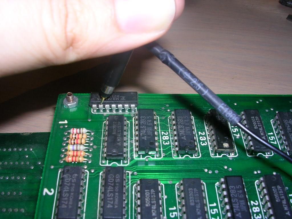
This chip is a hex inverter chip and seems to be almost the last lump of logic in the video section, and when I shorted an input signal to its gate output pin I got me some blue!
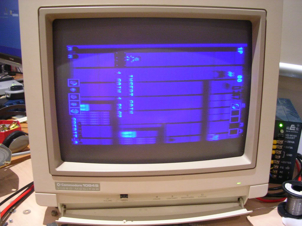
Piggybacking a good 74LS04 on the installed one woke up the gates and all the colour channels lit up.
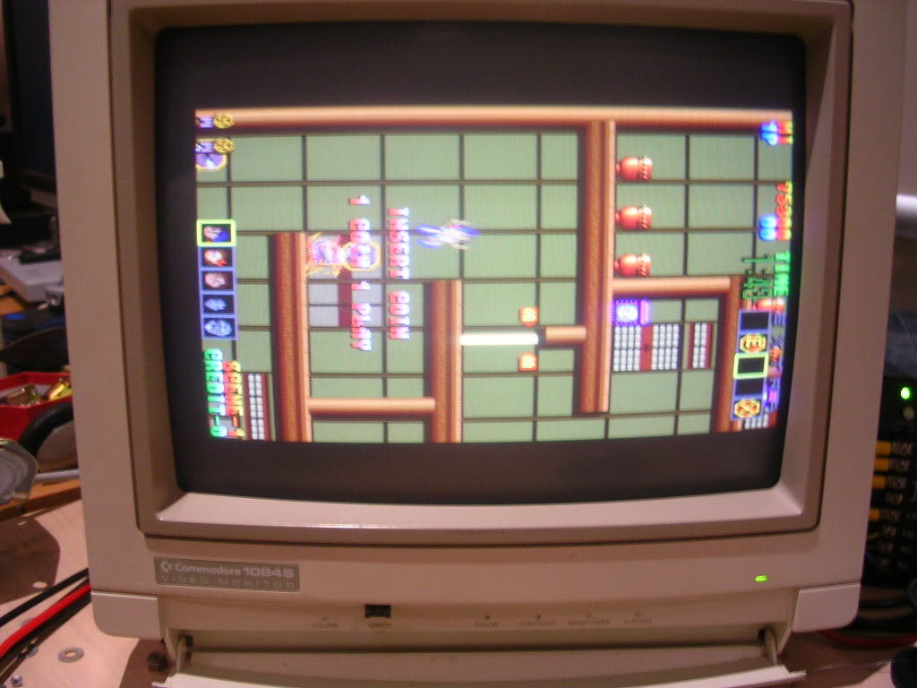
So the dead chip was desoldered and a good one from a scrap board soldered in, except all I got was this when I powered up..

..a parked board, the audio Z80 was stuck in reset again. Touching the mashed resistor brought the game back to life again but it was very touchy. The bodge had to be fixed properly, again it was an easy solution. Next to the Z80 was a 10uF 16V cap, a resistor, a diode and a 74LS14 chip, a combination often used to very slightly delay the Z80 from starting up until the power has stabilised on switch on. Capacitors only conduct when they are charging, once full they stop, the charging delay is the basis for the simple reset system. On power up the capacitor starts to charge via the current limiting resistor, while charging the anode goes to 5V, which is connected to one of the gates in the 74LS14. Again this is a hex inverter, in fact it is virtually the same chip as the LS04 other than the fact it transitions much more quickly. As it is an inverter when the input is high the output is low and its output is tied to the /RESET pin. The "/" denotes that it is "active when" low so when low the CPU is in RESET, the handbrake is on! Once that cap finishes charging it stops conducting so the anode goes low, the hex inverter does it's thing and the output goes high - the CPU comes out of RESET, the handbrake is off and the board starts. The capacitor in this case was knackered..
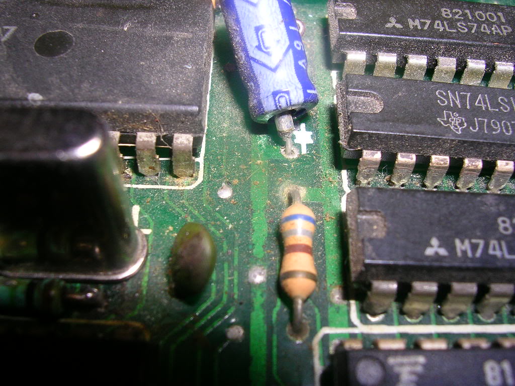
... a common enough problem, it has been wrenched to one side ripping the guts out with one of the legs. Once replaced the reset circuit worked perfectly again, no need for smashed resistors rammed up against the /RESET pin anymore. The half resistor gave the same result, it tied the Z80 pin high and acted as a current limiting device all in one, the only thing missing was the delay, which might explain why the board gave no sound in one cab, the Z80s might have started running in the milliseconds before the power was stable, ending up crashing the board before it could play the tune, of the smashed resistor might have not been making good contact at that point.
Next was to tidy up the crystal, leaving components like this on very long legs makes them far more likely to get caught on things, or worse, they get twisted and their long legs short out. Whoever fitted this had totally buggered the PCB plate through holes, but as I had about a mile of leg to work with I could fit the crystal flush on the board and use the legs underneath to connect up where the tracks once ran.
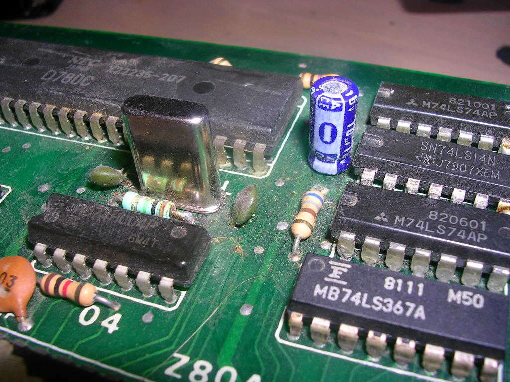
The final stage was to tidy up the audio amp and mixer area of the board...
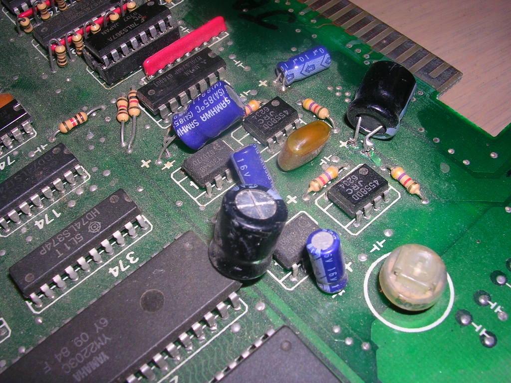
...although 160V caps did the job they were far too fat, and again they were badly soldered on with about a yard of leg on each side. In most cases they were soldered to the plate-thru hole with a blob of solder, the legs did not go through the holes at all, and whoever removed the originals had ripped up a track that was bent up off the board and badly reattached with more solder blobs to the new cap leg, the other leg was badly soldered in the hole and was loose.
They all came off and 10uF 16V caps fitted in their place, one badly fitted 470uF 16V cap was reused as it was the correct rating and in good nick.
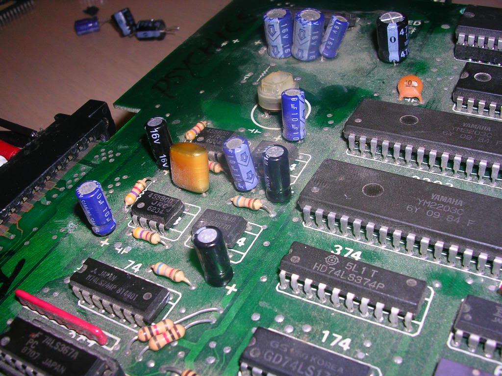
Once powered up the board ran flawlessly and I was even greeted to a new audio channel that had not been present before, presumably the loose cap at work, seems to be related to one of the op-amps, haven't bothered to trace it out.
I just need to find out what the value of the smashed resistor is, clearly it is there for a reason although it doesn't seem to be too critical as the game has been running for over an hour without missing a beat.
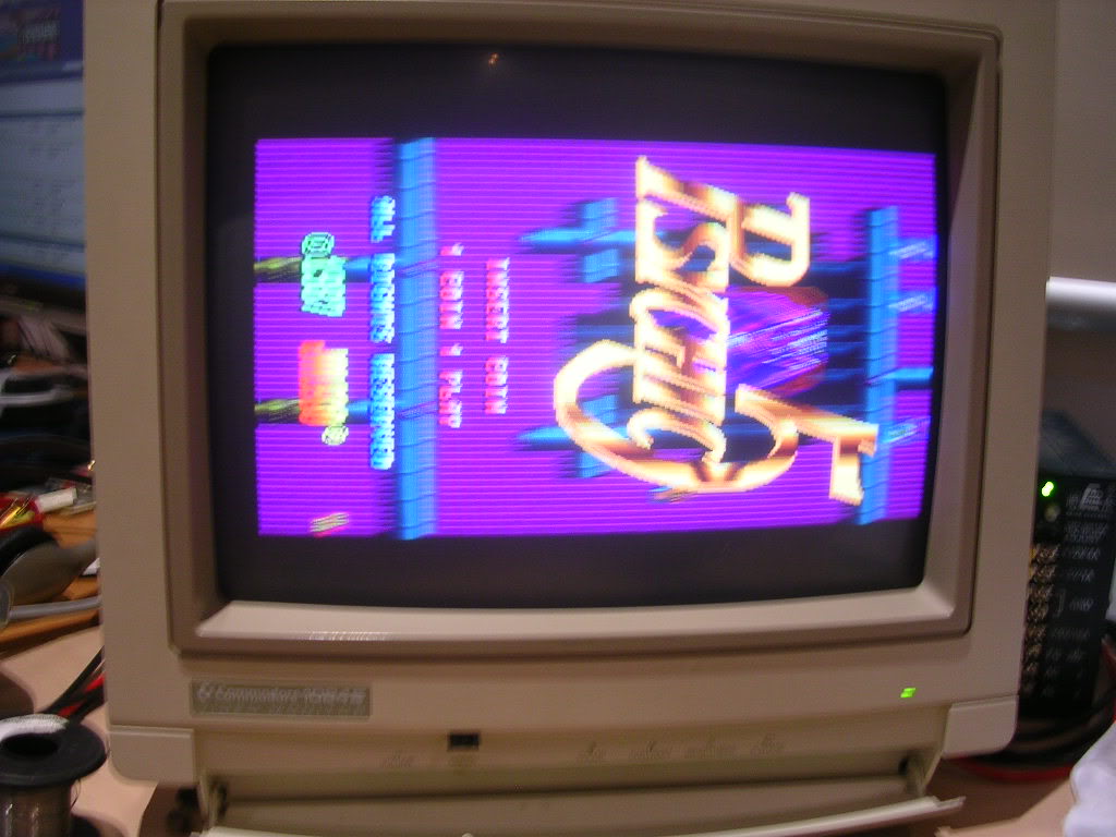
Crap photo I know, but she's fixed, cracking game music too!
Update - the missing resistor was a 220K ohm 1% tolerance, PinnyParlour took some photos of his original board and it is very similar in that area. It seems to be part of the reset circuit and was clearly designed to be there for a reason, so now it is again. Managed to straighten out the bashed in Z80 pins and gave the board a go over with a paintbrush, the underside of both boards was caked in dust.
All back together, all healthy, ready to hit the road next week.