PCB Repair Logs Psycho Soldier
Psycho Soldier
 |
|
| Manufacturer | SNK |
|---|---|
| Year | 1986 |
| PCB Image | Reserved |
| Pin Out | Jamma |
Repairer: Womble
Forum Thread: Psycho Soldier PCB Repair
This board popped up on Ebay a while ago, I was outbid and kinda regretted it afterwards, so when it was relisted for some unknown reason I paid it a bit more attention. Did I outbid anyone on here?
Short Version - board would not boot, single image of crap resetting on screen, constant coinup noises.
Bad 74LS157 at 8A on middle board. Bad 74LS157 at 8J on middle board. Bad 74LS245 at 6B on middle board. Bad 72LS32 at 2G on top board. Bad 74LS153 at 1A on top board.
Long Womble Version
The board was listed as faulty, the seller saying it displays coloured blocks on the screen, well it didn’t. It displayed this screen with constant resets.
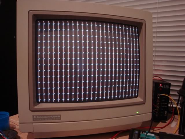
The screen was actually flashing white between resets, and it was so rapid that it gave the image a torn up jagged look as it was rescanned on the screen.
The clean image above is more to do with a fast camera than anything else. There was also an loud clicking from the speaker and the coinup sound playing every time the screen reset.
The KOLV blurb says the board is massive, and peppered with ROMs. Each board is not that large, but it’s a three PCB stack with twin triple connector ribbon cables at one end and a single dual connectors ribbon at the other end under the JAMMA connector, I was expecting more ROMs too.
PCB board stacks are a pain to work with, but at least the PCB underside is well protected being inside the stack, usually both boards chip sides are on the external edge, anything over 2 boards and it gets very hard to work on the board as you have somehow unhinge the boards while still keeping everything connected if you are to get to the middle one while it’s all running.
Anyway - at first glance the board was in very good nick, no visible damage or even chip surface scratching, there must be over 400 logic ICs on this board and all but about 6 are "F" branded, never a good sign, although they are often faulty in an obvious way which can help. There was one damaged electrolytic that I removed and replaced.
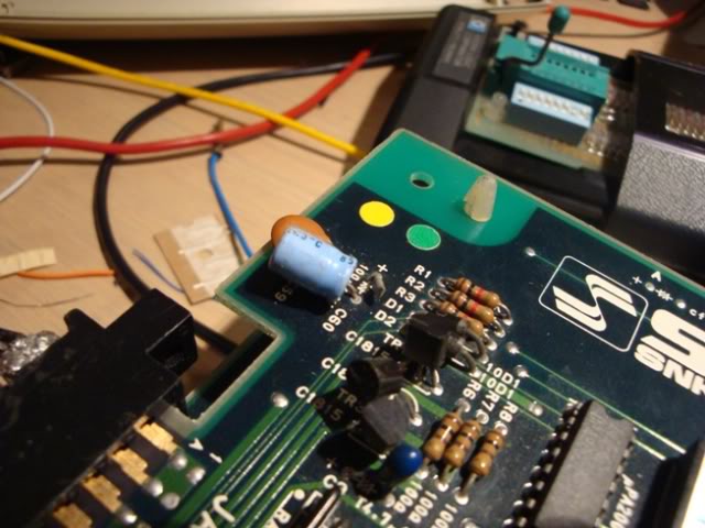
Straight away I hit the RESET pin on the 3 Z80s expecting to see them bouncing in time with the resetting screen, they were stable and high which was disappointing. Either this board doesn’t have a watchdog circuit, or the CPU was crashing and recovering on its own, which with Z80s is unlikely. Every other pin on the Z80 looked OK.
So I checked the voltages on all 3 boards and they were good, a level 5V at the furthest reaches of the board and 5.2V at the Jamma connector, all good there.
I had searched for a schematic for this board for ages and come up with nothing; I am not sure many SNK diagrams ever made it out into the wild. I did find information in the MAME driver file that was pretty handy, it detailed which of the ROMs were program code, which were gfx data and which were sound. When the MAME roms are fired up the board first checks RAM and then ROM for Z80 #1 and then the same for Z80#2, Z80#3 on the board is marked as "sound" in the silk-screening which is useful.
From what the board was doing I assumed that it was trying to run the CPU #1 RAM test and failing, so to rule out the ROMs I dumped them and they all checked out. I made an attempt to see if I could isolate the problem to one of the boards by disconnecting the ribbon cables at various points, it didn’t really help much although I did get screens of crap containing graphics elements...
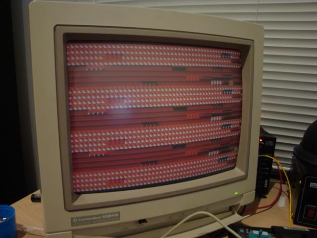
and even some whole sprites – it suggested there is life in there somewhere at least.
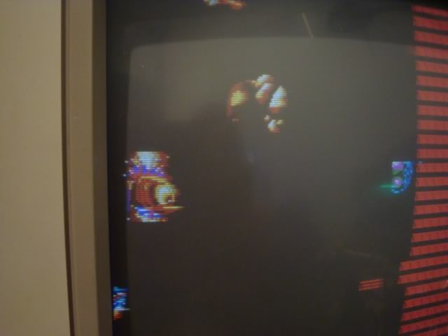
Basically I was hoping that it would get further into one of the tests with one of the ribbon connectors removed, ie was something on one of the boards preventing a test from running and when disconnected it would get a bit further into the boot process.
I probed around the top board for a while and found a few missing lines, the LS04 at H3 had no output on pin 2, the gate input on pin 2 had no input, this traced to the LS74 at E4 (but that is an input too) and then to a pin on the fat custom chip in the sound area of the board. This custom has had the markings ground off, and with no schematic I had no choice but to ignore it for the time being and hope that chip wasn’t the fault.
Flipping the board stack over I probed around the RAM chips and found a few odd things, pins carrying the signals IO1, 3, 5, 7 were held high, the LS273 chips associated with them at 1M and 1N had no clock on pin 11, both were high. These traced to an LS138 at 4L which had all its outputs tied high, clipping the logic analyser to this chip showed it was working correctly, pin 4 was bouncing in time to the screen resets.
This is the main trouble with a board that is bouncing, a lot of the activity you find is because of that bouncing, usually you try to silence the watchdog to get some peace and quiet but this board didn’t seem to be watchdog-resetting so I had to put up with the noise. In many ways a board that instantly locks up, or does nothing at all is far easier to work with than a board that is a quivering mess.
I went back to the Z80s on board 1, Z80 #1 and #2 were socketed, so I swapped in known good Z80As but that didn’t change anything, I removed Z80B to try and work out which RAM chips were associated with Z80A, but with the resetting there was still activity on all the RAM chips address lines so it didn’t really help. A missing CPU also causes a lot of chips to have floating inputs and this can look like a fault on its own.
There is no RAM on the top board, and only a few 6116's on the bottom board, Sod's Law seemed to be in play meaning the fault was going to be on the least accessible of the 3 boards. The trouble was that although 5V and ground is carried on the ribbon cables, it is also on fairly chunky looking link cables from board 1 to 2 and from 2 to 3 at the opposite end, conveniently the manufacturers used black wire for the 5V and red for the ground – the lead plugs are keyed and cannot be reversed, if I hadn’t checked the polarity my logic probe would have been destroyed. These link leads are presumably to take the current load off the thin wires in the ribbon cables. So I made a meter long link cable so I could hinge board one out of the way keeping the ribbons to board 2 connected and still power the lower boards from the top board. The only place I had enough room to do this was on the floor with the JAMMA connector connecting to one of my cabs, not ideal!
Started to sniff round the board and almost instantly found some smoking guns, clustered around 4 6116 RAM chips are 6 LS157s, the 157 at 8A had all 4 output pins floating and the 157 at 8J was missing 3 of its 4 outputs.
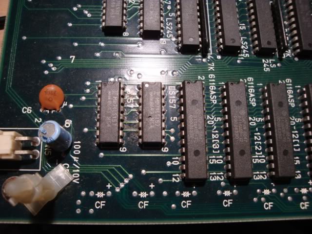
Piggy backing new 157s lit up these missing lines but did not fix the resetting issue, the sound effects did cease. In fact while probing around the area I did disturb the piggy backed 157 at 8A and the board started to sing to me! The sound track on this game is made up of about 10 samples of vocals. Clearly the crap on the line had made enough sense to the sound system that it was interpretted as a trigger to play one of the samples. Freaky, but it did prove that the sound system was working correctly. By removing and replacing the piggy backed 157s I got a variety of sound effects to play, including samples and the chip tune backing. So I soldered the 157s in place and the board became silent, still constantly resetting but no more cacophony of coinups.
I moved on to the RAM on this board, the system was going to be trying to test CPU#1s RAM and that had to be somewhere, the small amount of RAM on board 3 looked healthy if a bit unused. Hitting the address lines on all 4 chips with the logic probe showed a lot of activity on most chips but problems with the two 6116 chips at 8C and 8D. Both had address lines stuck.
8C had A6,A7,A8,A9,A10 tied low and 8D had much the same with one line stuck high. The other 2 6116s looked ok. Always suspecting the RAM I desoldered the two chips and put them through my eprom burners test program - both chips passed with flying colours.
While the chips were off the board I went round the empty pads with the probe and traced the stuck lines back to an LS273 at C5, it had an active clock and looked fine apart from the stuck outputs, so I desoldered it and tested it - it too was fine. With this chip off the board I went further and found an LS245 at B6, this looked fine too except for the stuck lines, so I pulled it off the board and tested it - it failed miserably. With the 245, the 273 and the RAM off the board all the address lines were floating. Clearly it was just the 245 that was jamming the addressing system for those two chips.
So I fitted a new 245, also a new 273, and resoldered the RAM back in place. Plugged it into my cab and powered up. The game went through its tests, passed all RAM and ROMs and the game started.
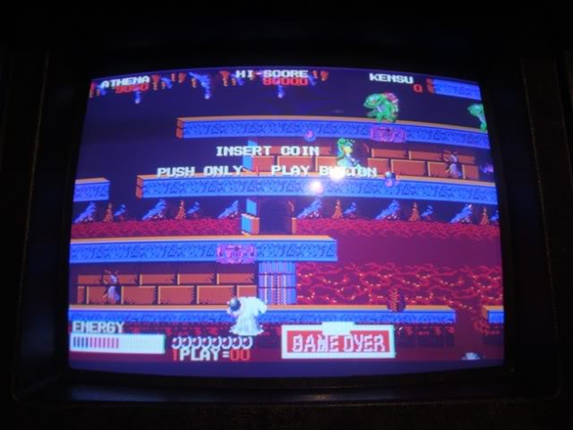
Initially everything looked good, the graphics were clean, no glitches, the sound effects, music and samples were playing, but the colours looked pretty strange. It also struck me that there were no enemy noises, ie no "hit" noises. I soon stumbled across an LS32 at G2 on the top board with a stuck output pin (held high). This line cuts straight across the board on a track about 15cm straight into the unmarked custom chip near the sound section, seemed a good candidate for the fault, and replacing it lit that line back up and all sounds were restored.
The main chr sprite still looked very odd tho, green hair?!? The star in her hair should be yellow, not green with a black trail!

so I fired up MAME to compare, and noticed a couple of things were wrong.
Firstly the stone background on the title screen was missing
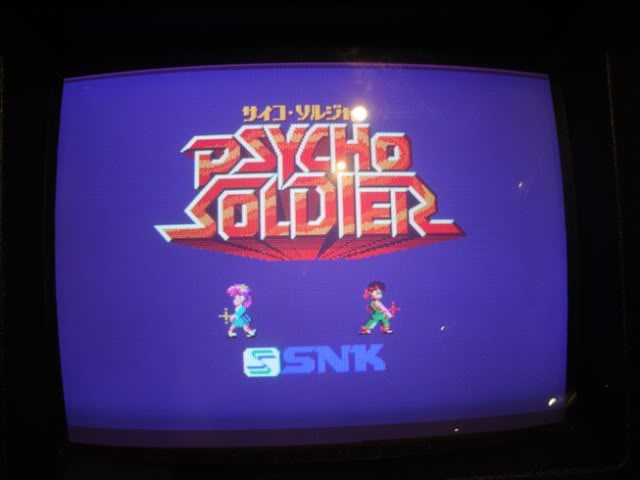
also the sprites were all coloured slightly wrongly and the back-drops looked odd too. The screen after the game splash screen with the two characters faces is coloured wrongly, the faces are purple not pink and it too is missing the stone backdrop effect.
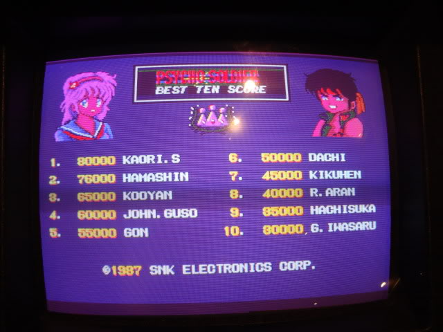
On the main board there are 3 colour PROMs, so I went around the board area near them and quickly found an LS153 at A1 that had missing outputs,
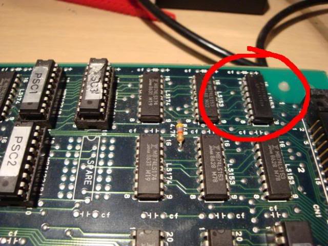
..so I replaced it and rebooted
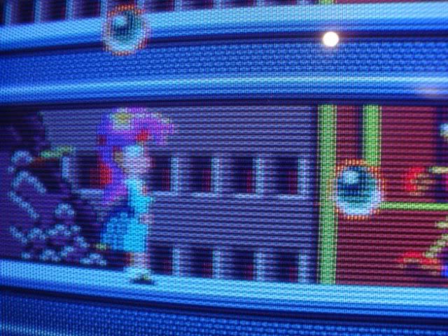
the sprites and the backgrounds were now perfect, but other faults remained, animated backgrounds are not coloured correctly and powerup gfx element the same.
I set the game into test mode and the 1st test is the colour swatch test, clearly something wrong here, the green is ok, the white is ok, the blue is very pale and the red swatch is pale green.
I am not sure where it is generating that test, as it would suggest the board can't do red, and that all the blue should be weak, but in the game the colours are bright and all are present. Clearly something is not quite right, it might be the colour PROMs themselves but I doubt it.
Probing around the are same section as the duff 153 I found I could alter the colours by injecting crap into the 153 inputs, also triggering the "clear" on the Ls74s I could bring up the stone effect patterning, it was all bright red but it suggests the data is there, on another pin the grey stone appears but the rest of the screen is garbled. This is what happens when I short data on one of the 153 pins...
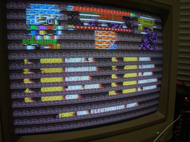
Replaced a few more 153s and the 174s in that area but it didn't change anything, my logic analyser shows the chips that are there are working ok but I may replace them anyway.
And that is where it is at at the moment, all in all its taken me about 10 hours so far, sounds a long time when reading the above, but hindsight is always twenty twenty, a schematic would have been very helpful, as tracing lines across multiple boards is very time consuming and frustrating work. At least the board is now working, my concerns about the unmarked custom were thankfully unfounded, still a bit more work to do on this, it probably is just a single fault that is left, but faults like this are the hardest to find. A board that is doing nothing gives you clues, a board that is doing 99% the right thing is much harder to work with, especially without a schematic, may be a week or two before I can get back to it tho.
By the way - the audio in MAME is not emulated correctly, the backing chip tune plays too fast, with the result that the vocals are out of time, sounds much better with the real thing
Update - I did replace all the 153s and the remaining 174 but it didnt change anything, the outputs are much cleaner on the scope but it hasnt changed any output. Am pretty sure that the remaning fault is not on the upper board, will need to track back to see what is connected to this area through the ribbon cable at some point.
Update:
Fired it up again this morning to have a go at finding the last fault, only to have it die before my eyes. It booted, got half way through the intro and locked up.
Powered it off and now it passes CPU A RAM and ROM, then goes to a blue screen with crap at the bottom.
Think I found the culprits, weird chips that I do not have spares of 74LS670s!@#! , time to place an order, am getting low on a few other things anyway.
Update:
Well I got my 74LS670s and they tested bad in my VP280, turns out the logic script that the tester has for 670s is incorrect so they were fine. Anyway - the recently developed fault was that it would pass the CPU A RAM and ROM tests and instantly lock up giving this screen.
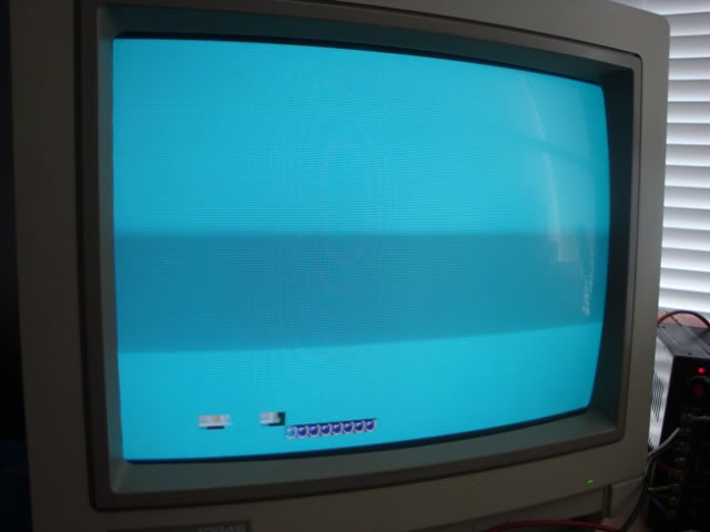
It should be testing the RAM and ROM for CPU B at the point it locked up so I had started off probing around what I thought were the right RAMs and ROMs, had gone down a blind alley as the outputs from the LS670s looked suspect, and my chip tester had given me a false failure on the test.
So I started again, the CPU, RAMs and ROMs are spread out all over the 3 board stack and its not easy to see what RAMs are tied to which CPU. I went round them looking for problems but when the board has crashed it is not easy to spot stuck pins on things unless its an output on a chip that has happy inputs. With SRAMs you cant really say what the address lines should be doing as the CPU is wedged so anything is possible, it looked a bit suss but was nice and clean so I moved on.
Found some RAMs with very nasty looking address lines tho, the 6116s at J1 and K1 on the bottom board, most of the lines were transitioning nicely but a couple looked ill, almost sawtooth waves that were only 2V peak to peak.
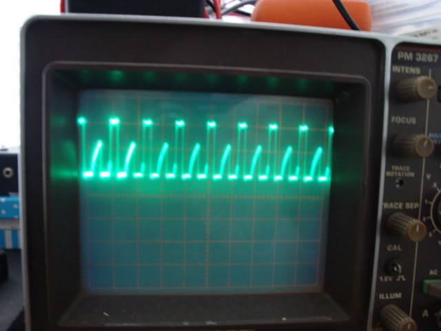
This board would be unrepairable without a scope by the way - the logic probe alone can only tell you if something is active, and these pins were active, but the pulses were ugly as all hell.
By pulling out the ribbon cable I could isolate the source of the signals to the CPU board. Traced them back to a 74LS244 and 373 pair at 4N and 4P, the 373 is an octal latch that is there to tidy up the signals and make sure the transitions adhere to the clocking signal, the 244 is a line driver/buffer that gives the signal enough oomph to travel across the ribbon cables to the 2 other boards. Ribbon cables and connectors involve much more copper than a tiny track on a board so the line needs to be driven harder for the signal to get to the other boards without attenuation.
The 244 was getting semi decent looking inputs from the 373 but a couple of outputs looked nasty.
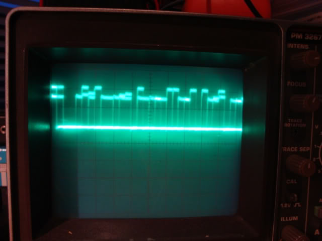
Both were Fujitsu chips so I pulled them out. Actually the whole damn board is Fujitsu chips so this may die on and off for years.
The 373 passed the test on my tester, the 244 failed the 1st test pass, but subsequently passed the 3 or 4 more tests I ran on it. I never put F's back on even if they test ok so I soldered in replacements. Unfortunatly it didn't fix the fault, but the signals looked much cleaner on the scope so it was not a waste of time. TTL logic systems can deal with a lot of crap on the lines as its all threshold based, as long as the messy signals transition from 0s to 1s as expected the next healthy chip will understand the signal and it will all still work. Both of those chips were on the way out so they needed retiring.
Went back to scoping around and found similar noise from the 244 and 373 pair at 8N and P on the CPU board. While probing on the 244 the board rebooted and started to cycle past the point at which it locked up originally putting a column of crap on the screen, I took this to be a good sign that I was in the right area. During testing I had been rebooting the board by injecting a rogue signal onto the RESET pin on CPU A and this scrolling crap persisted through these warm resets but the original static fault returned when I power cycled the board.
Anyway - desoldered both the 373 and 244 ...
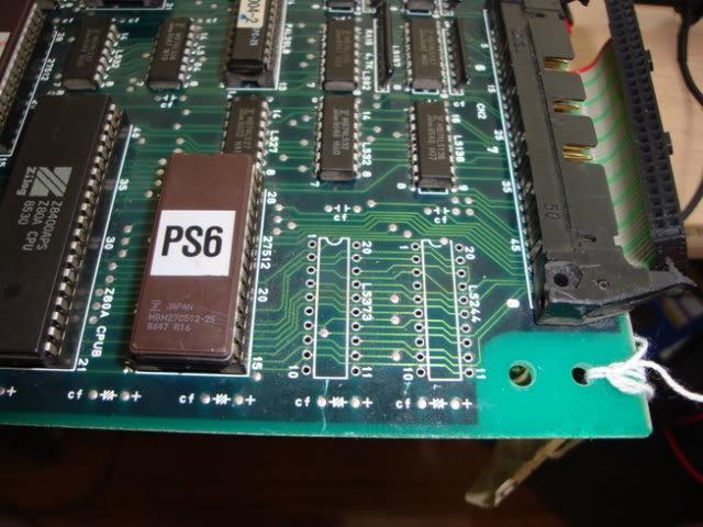
...the 373 passed the chip tester but the 244 failed.
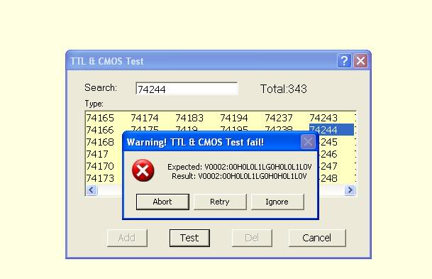
Soldered in chips from scrap boards and the board booted happily!
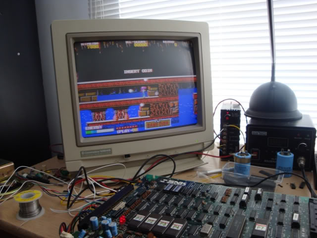
Still has the slight colour fault but at least I can now focus on that!
Update:
Well, nearly 18 months later and this is back on my to-do list, while googling for old 8 bit versions of arcade games, I found a photo of the same fault I had, the missing "rock effect" on the title screen. I thought some cheeky sod had been pinching my photos, so I went to the actual page. There I found the answer I had been looking for regarding the missing rocky background, which was described as looking like a "garage door", turns out it was a MAME bug all along! The fault on my board wasnt actually a fault at all, but the bug was fixed after anyone who cared about the game had used MAME to generate all the screenshots that now pepper the web.
This is what I was trying to get my board to do, and this is from KLOV...
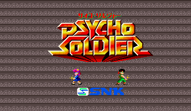
... and it is wrong, the background should be a flat blue colour. After the SNK driver was fixed towards the end of 2010 the title screen now matches what my board is doing, they also apparently fixed the badly mangled audio. I do still have a very slight colour fault to track down that affects the scoreboard, but the major fault that I could not find turns out not to have been a fault at all.
