PCB Repair Logs Wardner Bootleg
Wardner (Bootleg)
 |
|
| PCB Image | Reserved |
|---|---|
| Pin Out | Reserved |
Repairer: Womble
Forum Thread: Wardner (Bootleg) PCB Repair
Snapped up a Wardner board recently, sold as faulty, knew the seller so got the inside story. Board would only boot sometimes, or it would boot, run for a while, and lock up.
Wardner goes through a very long self test when booted, during which it displays a lot of colourful crap on the screen, with this board it didnt get very far before reporting "BAD HW". Sometimes it would complete its boot but mostly not.
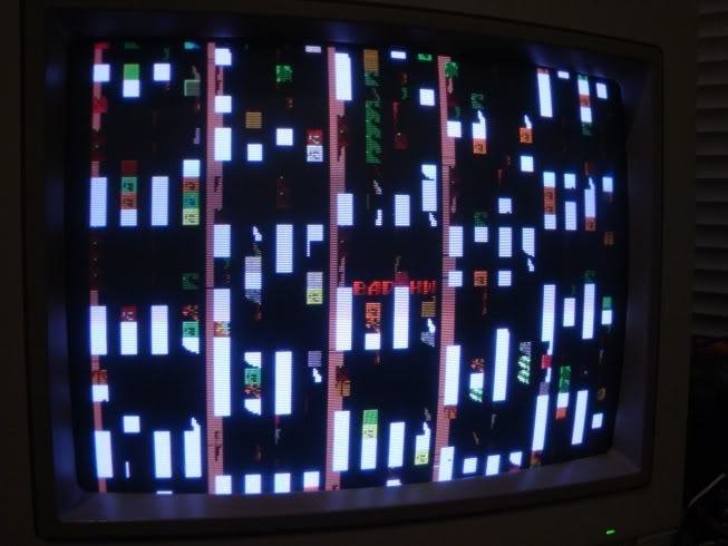
Its a pretty large board that is in very good condition, the board has been fixed a couple of times in the past but whoever did it did a very neat job. It is a large motherboard with two daughterboards on it, both use an array of pins projecting through the daughterboard which line up with dual wipe sockets on the motherboard. Its a cheap and cheerful way to connect boards but it doesnt age well, have seen a number of boards with flakyness before that were due to daughterboards connecting like this. It works well until the pins or the socket contacts oxidise.
So I gave both daughterboards a good wiggle, I was trying not to apply too much force, both were very firmly fixed. This made it better but didn't chase it away totaly, only when I managed to get both boards off did I find a handful of dry joints on the riser pins. Once I had resolsered those, I gave the pins a polish, squirted some contact cleaner into the mobo sockets and properly reseated both boards. The instability had vanished.
Initially I thought that was the end of it but the game did odd things. The sprites were unstable or just plain wrong. The icon you control to enter your initials was odd...
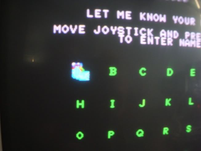
The sprite showing your position on the game map was a colection of whirling sprite quarters
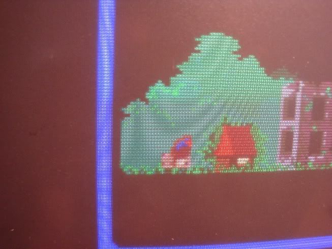
And the bad guy displayed during the intro was just a couple of fireballs
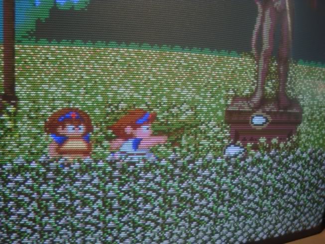
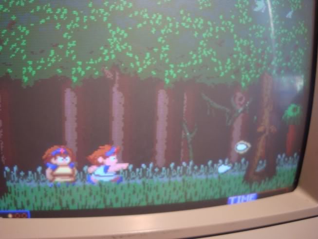
Sometimes the enemies would be correct and other times they scrolled through a couple of wrong options, back to the correct sprite and then round again.
So I went over the board removing, reading and reseating the ROMs, which didn't improve things at all but a reseat of socketed chips is always a good place to start.
Went round the ROMs injecting crap onto the address pins to narrow down which ROMs were doing what. Some crashed the game, some corrupted the lettering, some corrupted the background but the ROMs labelled W1 thru W4 caused the sprites to go crazy.
I compared the ROM dumps to the MAME set and W2, W3 and W4 were identified as being B25-02.ROM, B25-03.ROM and B25-04.ROM from the Taito set. The contents of W1 were not recognised. This might seem odd but this game is a bootleg and often there are differences, but I burnt a copy of B25-01.ROM to a 27c512 and dropped it in, the board booted but gave me a totally black screen with the "BAD HW" message again. I diffed the contents of W1 and B25-01.ROM and found they had large pockets of similarity, thankfully not great lumps of FFs which might indicate ROM damage.
So I went back to the address lines with the scope, interupting the address pins on ROM 1 actually improved things no end, the letter selector icon came good
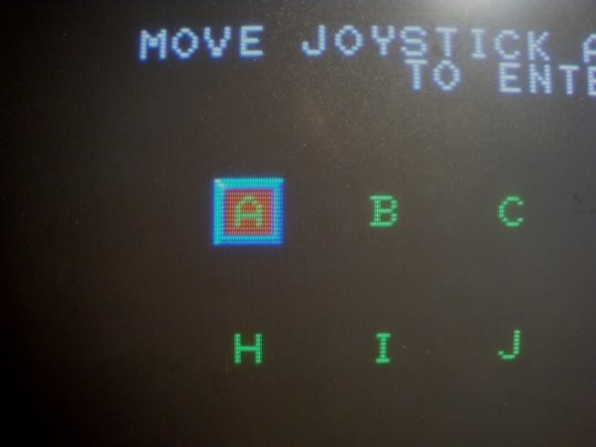
And I got half the bad guy back.
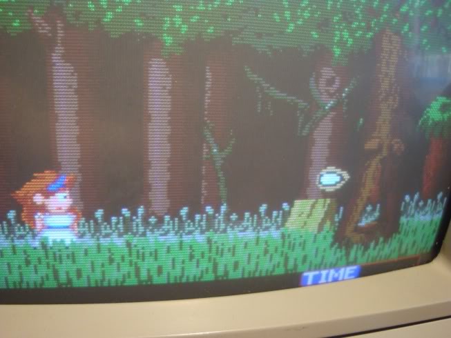
This is pretty much pure luck, that the junk I was causing on the address bus just happened to be close to what was needed at that point in time.
Most of the address lines looked fine on the scope
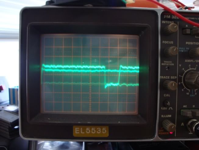
But pin 3 looked unwell, very subdued.
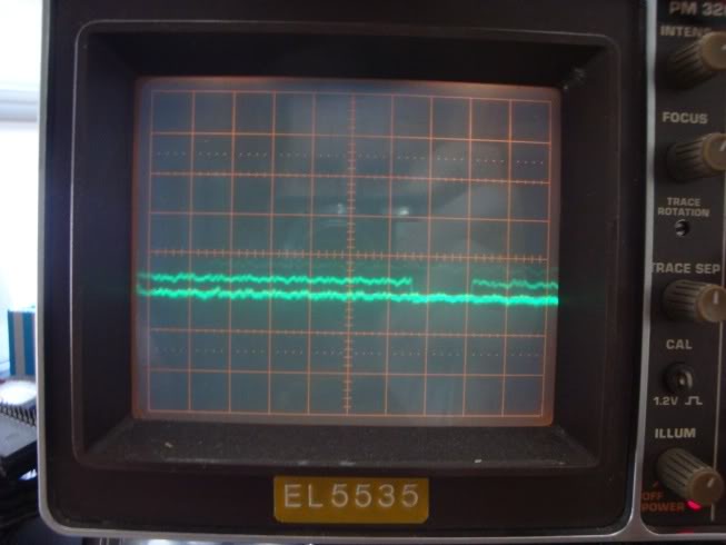
Address lines are input lines so I went over the nearby 74LS374 (often used on busses) with my meter set to continuity beeper and found that A7 (pin3) connected to pin 6 on the 374 at B10, this was the output pin of the second gate and the input pin signal looked fine. So I desoldered the 374 and expected it to test faulty, except it passed all tests.
So I powered up the board while the 374 was missing and hit the chip holes with the scope, all of them had activity on them except for pin 6 which was at logic zero and quiet.
Spent a while removing the ROM chips and rebooting, noticed that the track to pin 6 lit up when ROM 1 was not present.
When ROMS 2,3 and 4 are there it is normal, when ROM 1 is there, either alone or with 2-4 the pin goes to logic 0.
Its the ROM chip itself that is dragging down the address bus line A7!!!
I put the 374 back on the board and confirmed the theory, everything looks fine on the scope when ROM 1 is missing, of course the game doesn't boot with out ROM 1, in fact there is nothing displayed. As soon as ROM 1 is put back the output of the 374 to W1's A7 gets squashed.
So I burnt the dump of W1 to a 27c512 and dropped that onto the board, and this fixed the game.
Map icon guy is back..
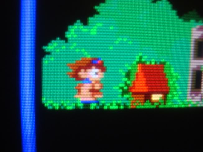
As is the bad guy at the start..
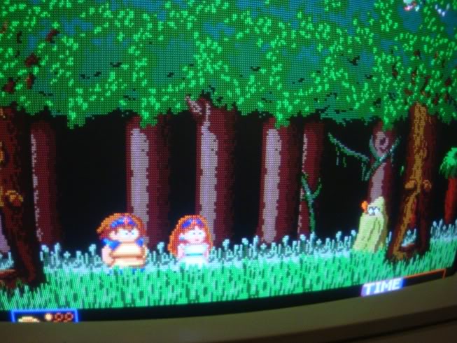
I consider myself quite lucky that I got to this board before the W1 died totally as MAME doesnt have the bootleg roms. I was actually surprised that the ROM could be faulty enough to drag an address line down, yet still be readable and have non corrupted contents.
If it had totally died I would have no other option but to try and track down someone else who has the very same board as well as an eprom reader - which may or may not be an easy task. W1 clearly contains sprite data as well as boot information, I assume the B25-01.ROM does hardware tests on the Taito hardware whereas the data in W1 has to know about any logic differences or perhaps is just the same data unencrypted, eitherway the board is perfect again.