PCB Repair Logs Asterix
Asterix
 |
|
| Manufacturer | Konami |
|---|---|
| Year | 1992 |
| PCB Image | Reserved |
| Pin Out | Jamma Pinout |
Repairer: Womble
Forum Thread: Asterix PCB Repair
Bought a few faulty boards recently from a member on here, he had a Konami Asterix board that he was thinking about selling, but decided he really wanted to keep it for his collection - trouble was it was faulty so he asked me if I would have a look at it.
It had graphics issues, part of the title screen was mangled..

.. the Chief's face is a mess.

The main character sprites have corruption of varying degrees, from mild..
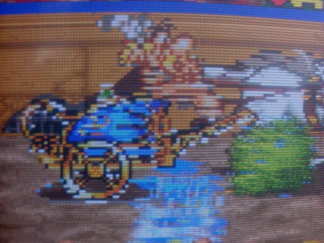
..to messy.
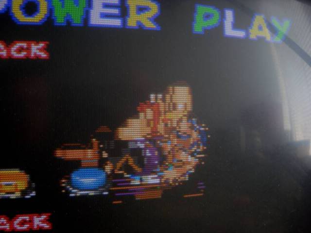
The board would also sporadically reset, which I initially thought would be related to the corrption issue. The gfx mangling didn't look like anything that was instantly explainable, the sprite edges were very jagged..
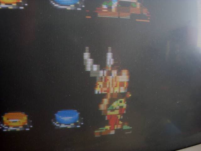
..and surrounded by sparklies i.e. pixels that flick on and off. Mask rom faults usually put vertical lines through the sprites so I thought it might be something more serious. I am always concerned that faults on these boards are related to the custom ICs, impossible to debug, only option is to replace them, which as they are surface mount and are only available on other boards means I tend to write the board off.
Anyway - the boards has a microswitch that puts it into diag mode, and one of the options is to check the mask roms, so I did, and it came back with the report that 3J was faulty! Thought it was going to be an easy fix, I desoldered the chip, and dumped it with my eprom reader as a 27C160. The chip read and the dump was recognised as a perfect copy of the correct game rom - arse!
Fired up the board with out that mask present and it did look better, clearly half the data was missing so it was fairly "wrong", but I thought it looked a bit neater. Having just fixed my Wardner board which turned out to be an EPROM that would read fine in my reader but would drag the bus down when it was on the PCB I had concerns about this mask rom might work fine when driven by my tester, but was borderline when on the board.
In a perfect world I would have burnt a copy of the MAME set data to a fresh 27c160 chip, fit a socket to the board and drop it in to rule out the mask rom totally. Trouble is I didn't have any 27C160 chips and fruity sized eproms tend to take about a week to arrive from which ever part of Asia or the US I find an Ebay seller with some.
So at this stage the custom chips was still suspect, as was the mask rom itself, not much progress really. So I start buzzing through the Address and Data lines, the lower 16 address lines go to the custom chips (which according to google are 16bit sprite generators), and the upper 3 lines, A17,A18 and A19 go to a couple of 74LS153s. The graphics issue could well be that the mask rom is being given the wrong address locations and is therefore pulling the wrong data out which messes up the sprites. I can't do much with the custom IC connected address lines but on my scope the output of the 153s looks rather weak. So I desolder them and they test OK too! With the address lines partially proven, and the rest relying on the custom ICs I move on to the data lines, the outputs look perfect on the scope and as they connect to the same custom ICs I can't really do much with them either. So I turn to the last resort - the sprite RAM, interrupting the address lines to the pair of TMM2018 SRAM chips causes the sprites to go nuts, so a fault in a few cells of these chips could explain the slight corruption, so I desolder these and they also test fine. Faced with so many dead ends I end up fitting sockets to the SRAM locations and installing known good SRAM chips - no change! I even fit sockets for the 74LS153 chips so I can isolate the output pins and drop in known good chips, no change. With the 74LS153 output legs bent so they don't make contact I can see that the relevant address lines on the masks are silent - this is good as it rules out any other chip from interfering, but doesn't actually give me any leads to fix the fault.
At this point the board starts to gather dust, I was idly flicking through ebay one night I see an Asterix board that VectorGlow was selling in the UK, he also fixes boards and the auction says that his board was faulty originally. It was a long shot but I emailed him and although the fault was totally different he makes a very useful comment, he has seen board diagnostics flag one mask as being bad when its actually only bad because another mask on the bus is flaky. This is pretty much what was going on with my Warnder board, one eprom ruining the bus for all the others that share it. So I desolder the mask rom at 1K and put that on my tester - it dumps but the dump is corrupt!!! WTF? this is the mask rom that the onboard diag says is fine, yet the one it says is faulty checks out as being perfect.
So I put the good mask rom back on the board and fire up the diagnostics again with the second mask rom physically removed - the bloody board says that the missing mask rom is perfect, and the one that is present is bad.
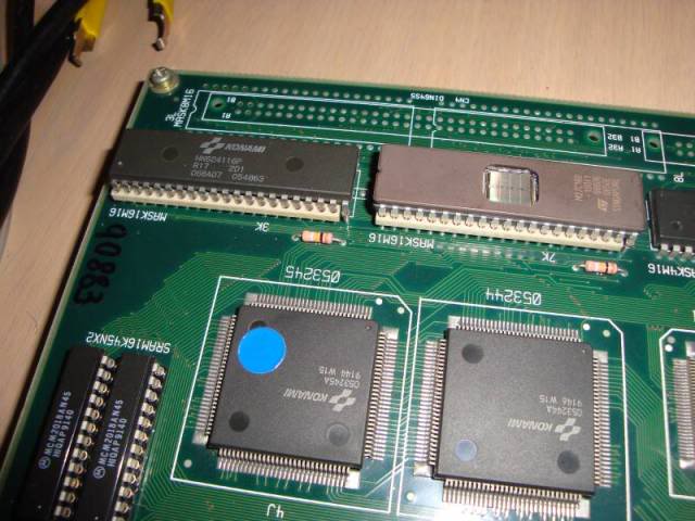
The diagnostic code has got its chips mixed up - when it says 3K is bad it should say 3J and visa versa.
When 3K (board says bad, I say its good) is on the board and the other one is physically missing the graphics are much much tidier, a lot of the colour info is wrong but there are no sparklies and nothing looks corrupted, in fact the bits that were a mess on the splash screen originally are actually missing now which is a very good sign - the messy bits all travel with that mask rom!!
So after a wait for the postman to bring me some 27C160s, I burn a new copy of 3K, drop it in and fire it up and the gfx problem is fixed.


Now I had originally hoped that the resetting was somehow related to the gfx corruption.
Unfortunately the problem was now worse, a lot worse, so much so that the board would hardly ever get through a boot. At the point it should go to the title screen where all the characters line up but it would instantly reset.
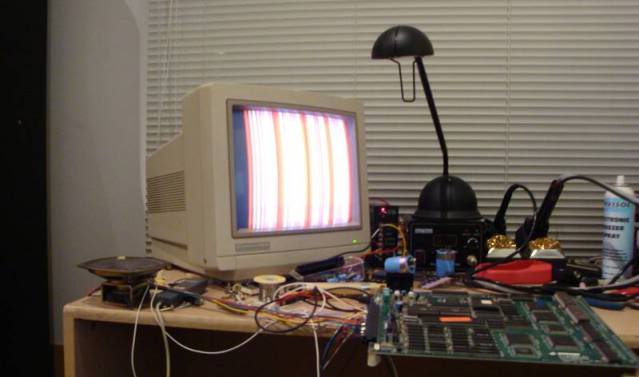
Logic would suggest that it was the newly installed 27C160 causing the issue, but even when the original masks were back on board it did the same. The reset line to the 68000 would flick at the point of reset and this is driven from a Konami 051550 custom 24 pin SIP chip , it had been badly bent to one side and someone had reflowed solder where it joined the PCB on the parts side. The solderside was untouched so I thought that it have actually been snapped off and reattached.
Faced with a new fault and a 051550 that looked bodgy I took it off the board, it actually was the original chip but I replaced it with one from a scrap TMNT board, again no change. Suspecting it might be the game code eproms causing real crashes I dumped them, and when they checked out I replaced them to make really sure they were not involved, but no change.
I spent a while probing around the board in between having goes on the game when it would rarely pass a boot, I noticed that if I coined up the board as soon as it was coinup-able then I could play the game for quite a while without any crash, but if I left it in attract mode it would reset within about 10 seconds. This smelt to me like a rom problem, i.e. it can run the game but the attract mode code is duff. Having already proved the main program EPROMs I moved onto the pair of mask roms by their side at 7c and 7d. I found that if I hit pin 20 with the scope the board would not crash, and if I ran my fingers over the legs on the 5V side the board would crash. So I desoldered them, put them in my tester and it complained about a couple of pins being out of spec, but the dumps were actually fine. Unfortunetly both chips came up with the same pins out of spec, which didnt seem very likely, and is probably due to them being masks and not the exact 27c512 chip my reader was expecting. Anyway, I fitted sockets, burnt the contents to a couple of 27c512s and was semi hopeful that would be the end of it, but the board did exactly the same thing as before, boot-crash-boot-crash-etc etc etc. Except now touching pin 20 with the scope had no effect at all. Clearly something on the board was very very sensitive to touch, and throughout the fix so far I had aggravated it somewhat and made it worse. The board was so damn sensitive that I would get random false positives all over the board while looking for areas that caused crashed. The JAMMA connector would seem to be the fault one minute, then it was a custom on the other side of the board, then it was glitchy when the CPU was touched. I took the board feet off and laid the board flat on the desk to try and get some stability to it so I could go round the board tapping things, it didn't help, most of the time the board was just in its crash loop anyway so I had no way to try to cause it to crash as it was already doing just fine on its own. Faced with a haunted board that was beginning to take the piss, I got my jewellers eye glass out and took the board into the bathroom where the spot lights are very bright. I went over every single custom looking for any pins that looked suspect, daylight is the best light for this as the reflections off shiny solder is worse with artificial light for some reason. On the very last chip I went over I found one leg that was very very slightly different, so slightly different that I nearly missed it.
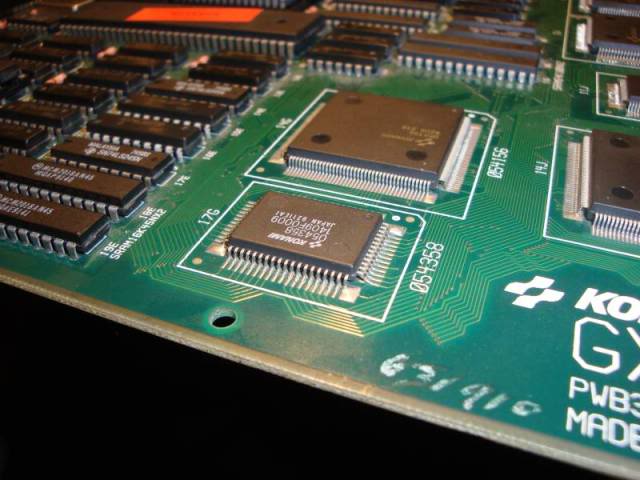
The solder had wicked up the leg and looked rather crystaline instead of the nice matt grey on all the other pins. The leg also was not quite down onto the board as far as the other legs, perhaps half a millimetre raised. To the naked eye it was virtually invisible but with a magifier it looked like the solder might have coated the leg like a sleeve forming a dry joint.
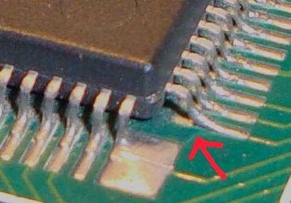
Fired up the soldering iron again and heated that pin with a tiny bit of new solder, I heard the pin crack into place as the solder melted and afterwards, besides being shiny it looked in perfect alignment with all the others.
Having powered it up again I now can't get it to crash at all, no amount of tapping, banging or flexing of the board has any effect. Its probably too early to claim victory on it tho, seeing as the fault crept it while I was fixing the gfx its possible I have somehow chased it away again without actually fixing it. Will have to see how she goes over the next few days, plenty of cold startups required I think.
Oh, and I booted the game with the diag button held down, which causes the board to flush an in-chip eprom somewhere and write some code from the main game eproms, that brought back a load of samples I didn't know I was missing, including the "konami!" cry as the logo appears.
Hopefully this one is now fully fixed, its actually a very very nice game!
Update - its fixed, hasn't crashed once since