PCB Repair Logs Ikari III The Rescue
Ikari III - The Rescue
 |
|
| Manufacturer | SNK |
|---|---|
| Year | 1989 |
| PCB Image | Reserved |
| Pin Out | Jamma |
Repairer: Womble
Forum Thread: Ikari III - The Rescue PCB Repair
Couldn't resist an auction I found where a guy was offering a stack of faulty boards for $10 each. Most were crappy sports sims but I grabbed Ikari Warriors original and Cobra Command.
I have a misbehaving Ikari Warriors in my to fix pile and as its a 3 board stack I reckoned $10 was money well spent for a spare, as I was planning to swap the boards around to help isolate the faults to specific boards.
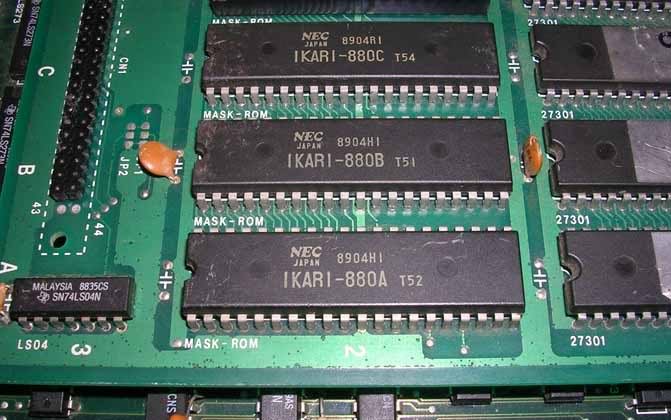
Except a 3 board stack with Z80 topping wasn't what arrived, I got a single board with a 68000 on top and a mask rom daughterboard. The only identifying marks were the mask roms that were silkscreened "NEC Ikari 880A" and the board was marked SNK.

Turns out this is the hardly ever seen "Ikari III - The Rescue". As its a horizontal game that uses rotary joysticks I was pretty happy, seeing as my rotaries had cost me $80 and until now I only had one game that used them.
Anyway - board was dead, blank screen, no sound.
Fix - Reset pin on the CPU was permanently held low, traced it to an LS14 chip at 1E that was shafted. All its outputs were tied low on all 6 gates so my plans to use one of the never used gates didnt get very far.
Only one was actually originally used by the board, its input tied to the +5V rail via an electrolytic. Its the CPUs handbrake really, ensuring the CPU doesn't start to run the code in the ROMs until the power supplies have stabilised and all the decoupling capacitors have been fed. Once the cap is full no current flows, so the input to the LS14 goes low, and its output should flip to high - except it wasn't, so the CPU was never allowed to run.
Didn't have an LS14 anywhere, so I fitted an LS04 - its the same chip layout, and a hex inverter too, but the LS14 has a threshold flipping point. LS04's like nice clean logic levels that you ain't gonna get out of a charging cap so an LS14 is really needed here. Anyway it allows the board to boot most of the time. I'll fit an LS14 when I track one down.
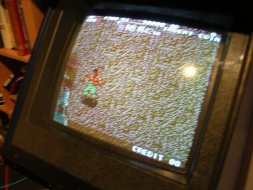
Getting more scrap boards soon. On boot the RAM/ROM checks passed and the game started. The graphics were not good though. The main sprite had sparkly pixels over his body, and the backgrounds looked unwell. The 1st stage starts off with the main guy up to his waist in a flowing river, with the water effect it looked not too bad as there were a lot of white pixels flying about, but once he made it to dry land it was a real mess.
Naff photo, but you get the message, the background is supposed to be desert I think.

The problem looked to be a RAM fault, and this board has RAM everywhere. I went over the board piggy backing good ram chips over the old ones but nothing improved. Started to look for a logic problem, suspected buffer chips mainly but again piggy backing did nothing.
Decided to dump the ROMS and compare them with the mame sets, trouble was none of my ROMs were recognised, this game is the Japanese version that's not known on the web it seems.
Thought it might be the graphics code in the mask roms, unsoldered one of the "Ikari 880A" roms, which turns out to be pin compatible with 27C040 eproms. It read fine but my board has 4 very large mask roms, whereas the mame set has a much larger number of smaller rom images so there was nothing to compare it to. I assume my big mask roms contain the "missing" roms in large data sets, the numbering on the board makes no logical progression so I cant guess which of the missing numbered roms are in my 4Mbit masks. Gave up on that avenue.
The dipswitch information on the web doesn't show a diagnostic mode as an option, and the test pin on the jamma adaptor does nothing with this board. The dip info did list an unknown/unused switch, so I flipped it and rebooted, and found the hidden diag mode. Nothing hugely useful like an indepth RAM/ROM tester, nothing beyond the usual boot test on that front. It did have the colour tester, which showed that 100% of the problem was in the green channel, that had white checkboard dots over the green test patch. Traced the green signal back from the Jamma edge connector into banks of 245s and 374s, piggy backing on these did nothing to improve the situation. So faced with a blind alley I went back to the 2nd rule of arcade repair - always suspect the RAM.
Piggy backing ram chips on ram chips again I found I could make the red patch go nuts with one ram chip, and the blue would go nuts with another ram chip. It was a shame there was no third chip I could blame green on. But I went ahead and desoldered the 2 6116 ram chips and put the in my tester. Both came up faulty, with a bus error. Feeling pleased at having found the fault I fitted 2 machined pin IC sockets and plonked in 2 known and tested good chips. Fired up the game and the same bloody problem was there.
Moved on to the other chips of the same type and removed a further 2 6116s, both tested faulty. Fitted 2 more sockets, added new ram and still the same bloody fault. There are 4 6264 RAM chips on the board, I removed one of those, tested it, it came up with "chip out of spec" on a number of legs. Fitted socket, new ram chip, same fault.
Was getting pissed off by this point, so moved on to the bank of 8 slimline 6116 chips, piggy backed a known good chip on each in turn and there was no improvement. Went over the bank one last time and when on one of the chips (3K-3J) I could sometimes get the green channel to work perfectly, but only every now and again. Once it was working, it stayed working, but as soon as I removed the new chip and the fault would return, replacing the piggybacked good chip would sometimes achieve nothing, but once in a while it would clear the fault again.
I could not get the old chip to desolder, the holes were tiny and the old solder was like stilton cheese, no matter how much new solder I flooded the joint with I could not get the majority of the pins to clear. Ended up cutting the bugger off and clearing the holes one by one, fitted a socket, dropped the new chip in.....
.... and the game was perfect!
I ended up putting the old RAM chips that my tester had flagged as faulty back in the board, and it still it works perfectly. I guess a negative test isn't as useful as a positive test in some cases.