PCB Repair Logs Indiana Jones and The Temple Of Doom
Indiana Jones And The Temple Of Doom
| Manufacturer | Atari |
|---|---|
| Year | 1985 |
| PCB Image | Indiana Jones |
| Pin Out | Atari System 1 |
Board 1
Repairer: Womble
Forum Thread: Indiana Jones And The Temple Of Doom PCB Repair
Another one of Borderstacey's boards, one of his favourites and one I remember playing when I was a kid on a ferry to France. It looked in very good nick but he had not been keen to plug it in to test it due to the state of the wiring, considering the % of faulty boards in the job lot he bought I guess it wasn't likely that this one would be a worker.
Am glad he didn't plug it in actually, the technical term for a JAMMA harness of this quality is "pigs breakfast", the shots here were after I had trimmed a lot of the loose wires off and cut off the uninsulated stubs of wire hanging off the power pins.
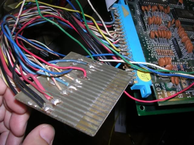
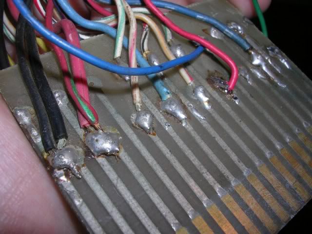
The jamma biscuit was about half as wide as it should have been, wasn't even long enough to get all the control lines on so I have no idea why it was used. Chances of shorting something out or applying volts somewhere unexpected due to all the loose wiring was pretty high.
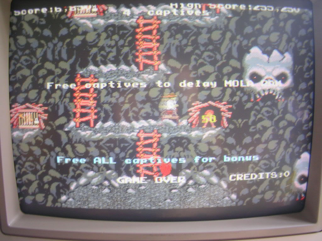
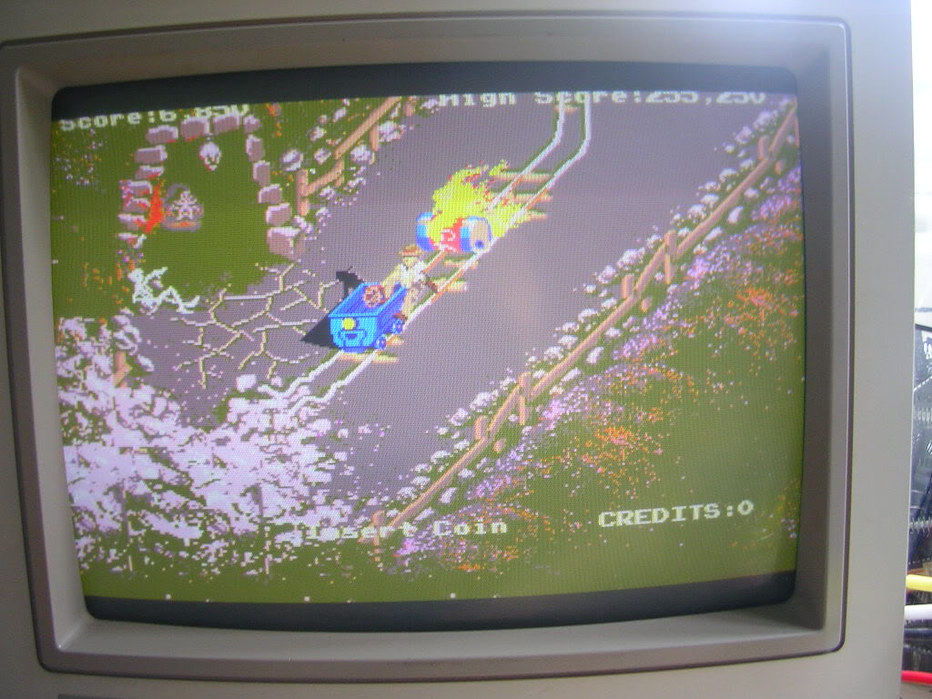
Anyway after a trim and a clean up with brasso it was useful enough to get the board to boot up, but the colours were wrong (at 1st glance it looks like its missing a colour channel but actually its not, the whites are white, and to get white you need all three colour feeds)..
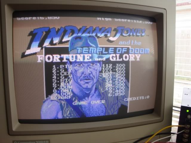
..there were lines through all the gfx, the sprites were drawn multiple times and were flickery..
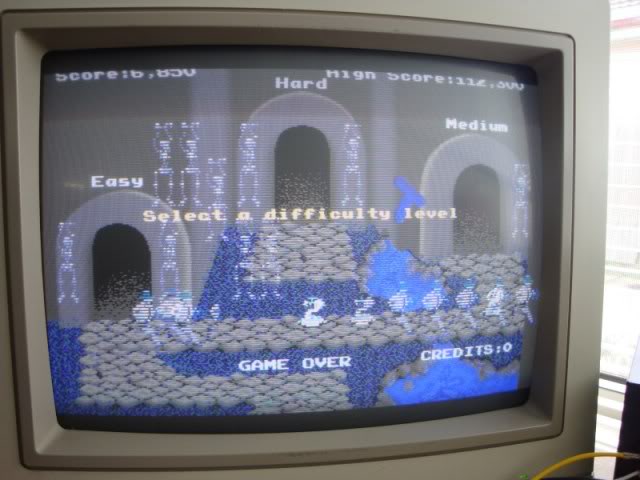
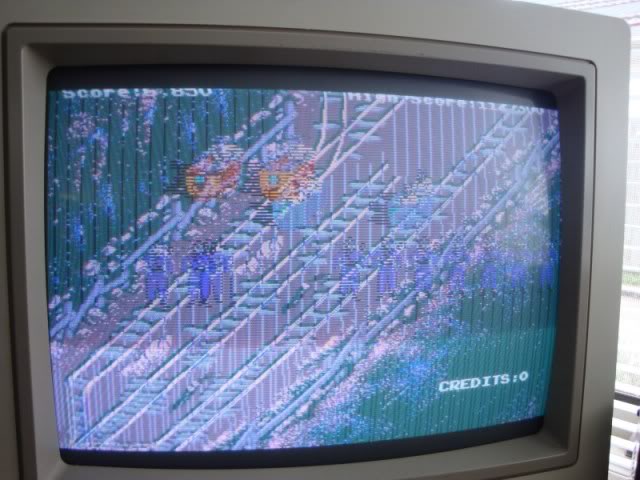
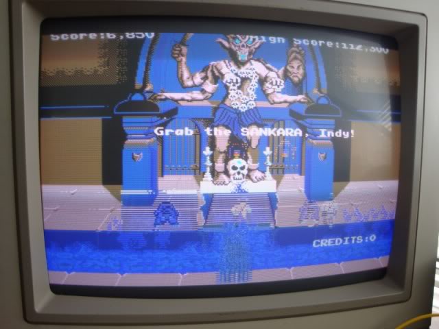
..plus the amp duo got stinking hot, so hot that it started to give off a burning smell. I took some wire cutters to the clown-loom and relieved it of the 12V connection, amp issues would have to wait.
The colour issue was simple case that whoever had wired the bodgy jamma adaptor had got the colour signals arse-about-face, so the red signal was going to blue input on the monitor, which is why the lava pit in the last photo has blue lava. The blue signal was going to the red input on the monitor making the mining cart red instead of blue, MAME is very handy when you need to see what the correct output is.
Now this board is not the standard Atari System 1 layout from what I can find online, it is 2 large boards in a stack with standoff pillars at each corner.
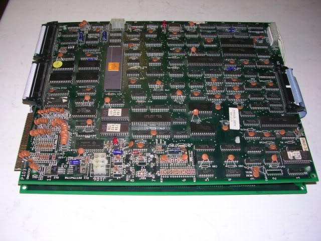
I assume it was never meant to be laid flat as the upper board is so heavy it has sagged over time and the upper board has scratched the lower board tracks in a number of places. Most of the scratches although looking nasty were actually ok, the tracks underneath had not been broken, except for this little lot...
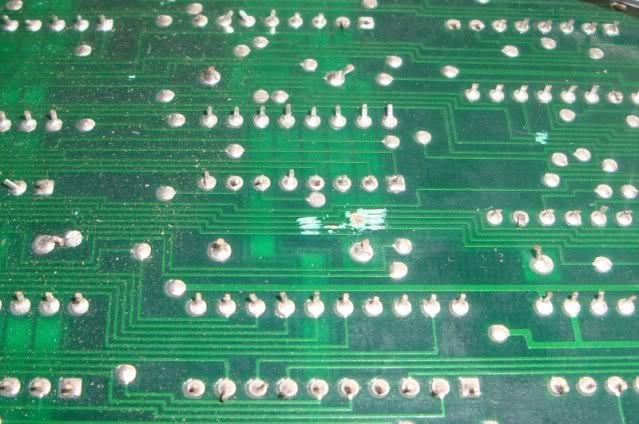
.. of the 4 tracks 2 were totally cut through, instead of trying to repair the area I simply bridged the damaged tracks with hookup wire.
With the tracks fixed and the bodgy loom modified so the colours are connected up properly I got this
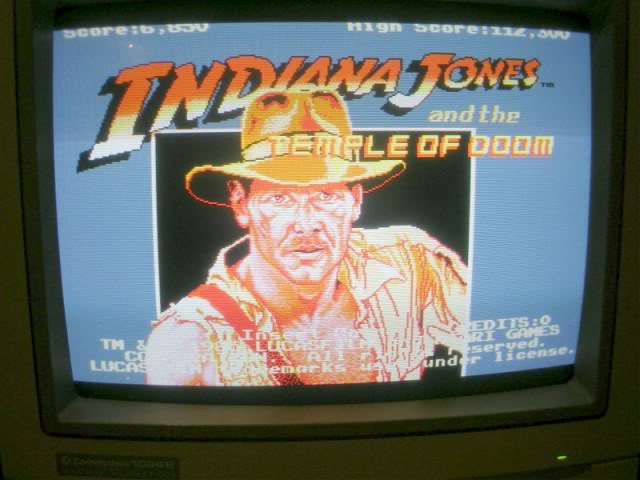
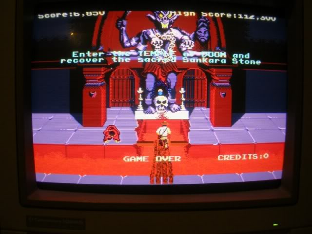
It looks good in photos but the sprites were very jerky, the movement was not smooth and the kids-in-cages sprites were jumping up and down.
I started to go over the board with the scope but the 5V line itself was very unstable which meant all the signals were unstable even tho the board was clearly working properly for the most part. I did actually wonder if the fault was simply cause by the unstable power.
Unstable power rails can be a sign that the PSU is struggling to keep the volts up, meaning the wiring between the PSU and the board is too thin. This board has an edge connector and a separate power connector on the top board. Mr Clown (it may well be THE clown from what I hear) had used the thinnest wire possible and to avoid the hassle of getting off his arse and finding the right plugs had soldered them directly to the pins in socket, the same had been done to the video out socket,
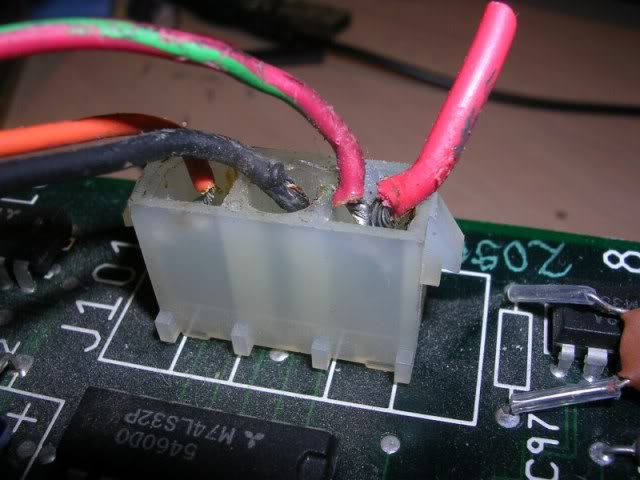
..(wires look quite chunky due to the zoom on this shot, compared to say the leg of a chip they were tiny)..
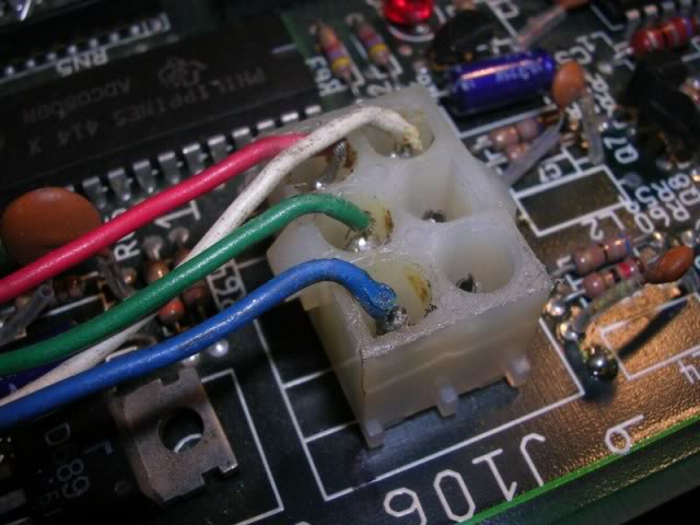
this annoys the crap out of me, especially when the board is in such good condition.
I was gonna have to remake the jamma loom at some point anyway to wire up the control lines so having tracked down the correct connectors (thanks Mikes Arcade) and put it off for a few weeks coz I hate making adaptors I finally got round to made the loom. Clearing the solder out of the sockets on the board was actually quite simple, my desolder station slurped it all out without doing any further damage to the socket bodies.
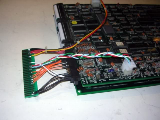
Half the reason I hate making adaptors is I have to do it neatly, and that takes time, but the end result is worth the effort especially for a classic board like this.
I powered up the board with the new loom (leaving the 12V disconnected at the PSU) and the power lines were rock solid, but the jerky sprite issue remained. Had quick look over the board with the scope, everything looked good now, was struggling to isolate the sprite gen area when I burnt my hand on a YM2151 chip, this is the FM synth generator chip and they do run pretty warm, but not that warm.
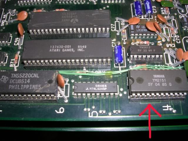
It was socketed so I powered the board down, pulled the chip and powered back up to carry on looking for the fault, problem was the the fault was gone.
This seemed so unlikely that I put the YM chip back in and got the fault back, pulled it again and the fault went with it. I pointed the scope at the pins in its socket and checked the volts were ok and I buzzed through to check there were no shorts to other pins that would explain its demise, everything looked ok. Oh well!
The lower board has a separate pinout for two channel audio as this game has stereo capabilities which were very rare at the time this was made, but looking at the tracks it was obvious that the output of 1 amp was carried to one of the board interconnects and this pair actually traced all the way to a couple of pins on the edge connector, so despite the stereo output there was also mono presented at the edge, handy for wiring up JAMMA adaptors. So I wired in the speakers and reconnected the 12V feed to the amps, dropped in a YM2151 off a scrap Capcom CPS1 board and fired it up. Was part expecting the YM chip to expire instantly, but I had music, sound effects and briefly garbled speech.
When powered up it would run through one cycle of attract mode with sound and then go silent. In fact it has one audio enable attract mode cycle and 4 or 5 silent ones before doing another one with sound, I was also slightly worried by the lack of speech by this point, thinking surely they would have shown off the speech in attract mode - apparently not going by the MAME version of the game, which has a slightly different attract mode but still no speech. A lot of the audio artifacts seemed very sensitive when touching the socketed 6502 CPU, giving this a good reseat drove away all the audio oddities, but it was clear I had to wire up the controls if I was to be able to test it further coz I needed to drop some coins and start the game.
The board had not used its speech snyth since I reseated the CPU and from MAME I knew the board should say "Welcome" in the voice of the bad guy when a game starts. Trouble was I could not find the pinouts anywhere on line especially as this board is not the common version of the game, I had to work it out myself. I used a lead with alligator clips on both ends, one end was clamped to a ground test point on the PCB and the other around the a screwdriver, then I could go along the unused pins on the edge connector with the screwdriver seeing what did what, I quickly found coin-up and start (which is also fire in the game) at which point the game said "Welcome" to me which was a relief as it meant the sound system was working. Once I was in a game I was able to track down the up/down/left/right pins, I wired these into the harness and had a few blasts on the game.
Next stage was to desolder the two amp chips which bolt to a single U shaped aluminium heatsink.
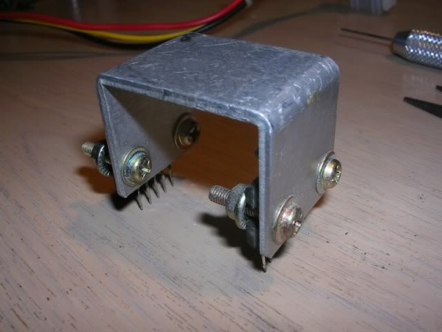
I figured that the second amp may be dead and causing the extreme heat issues, clearly the in-path amp was working, so I unbolted the second amp and soldered the assembly with a single amp back in at an angle so the rather lopsided heatsink would not be an issue while I was working on the board, this gave me sound without the too-hot-to-touch-heatsink issue.
The amp I removed turned out to be faulty, it just gets hot in another board that I could easily replace the amp chip in. Trouble was this board needs 2 amps to support the heatsink, so I cut the power, ground and audio input pins off the dead amp chip and soldered the remaining pins in, this means the game is now hardwired for mono but that's all it is ever likely to be used for, the amp chip probably died of boredom as it was, I doubt its ever been used in stereo if it was never in the official Indy cab. The amp carcass now provides only structural support for the heatsink but it solves that problem.
And that's it really, I cut a lump of insulating foam to act as a spacer bar to stop the two boards ever sagging together again, sprayed some lacquer on the other areas of scratch damage and set all the heatshrinking on the harness. I reckon she is good to go!
George you can have it back, but not til I have completed it 7 or 8 times ;o
Board 2
Repairer: Womble
Forum Thread: Indiana Jones And The Temple Of Doom PCB Repair
Snapped up a Indiana Jones & Temple of Doom PCB set recently, its one of the few PCBs left on my wishlist and has been there for a good few years.
Was sold as faulty with a couple of issues, originally it had been booting fine but crashing when it progressed from the title screen to the game demo, and was also crashing on coin up. The final fault occurred after the previous owner had reseated all the socketed chips, now it would not boot at all and just gave the message "Bank Switch Error"
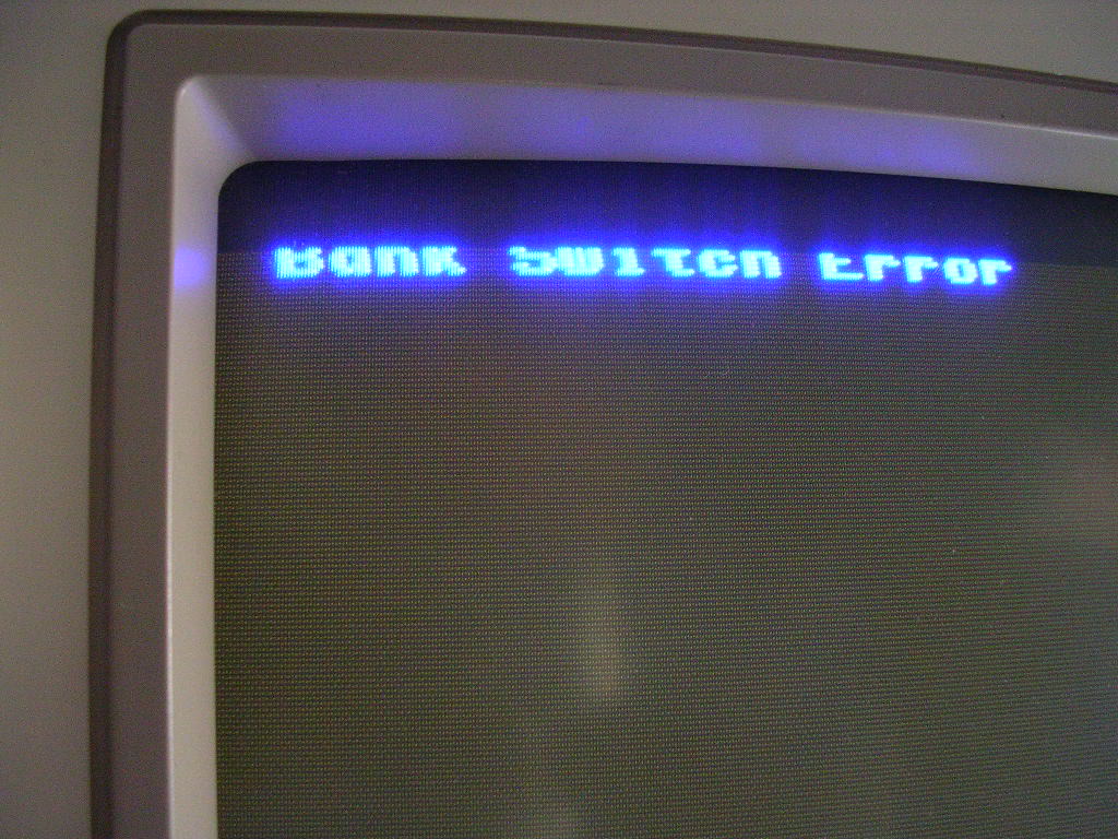
Reading around about the Atari System 1 architecture the most likely candidate turned out to be the Slapstic chip.
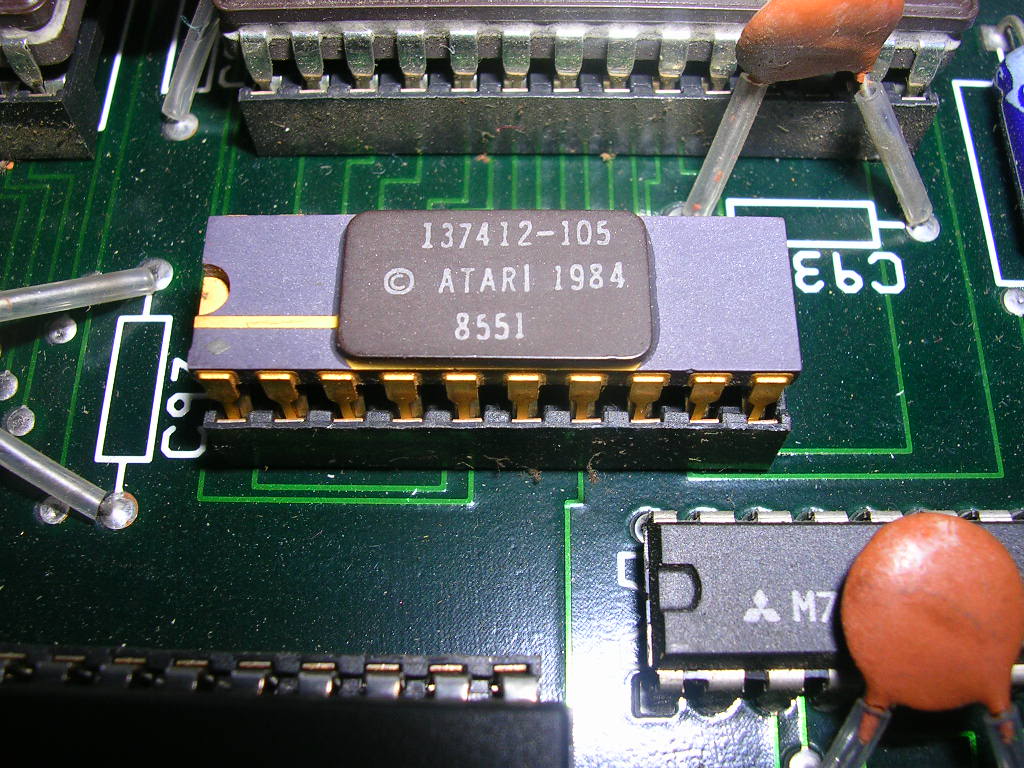
This is the security chip for the Atari System 1 PCBs and the security on the system 1 games is achieved by a complicated bank switching process which connects and disconnects lumps of ROM data to the CPU. If this turned out to be missing or fried then the board was not going to be a fixer. Each Atari System 1 game had a different slapstic and even Atari managed to lose the masks for these years ago so the only place I could get one was from another Indy board.
Thankfully Atari put a tonne of sockets on their boards so the slapstic was easily pulled...
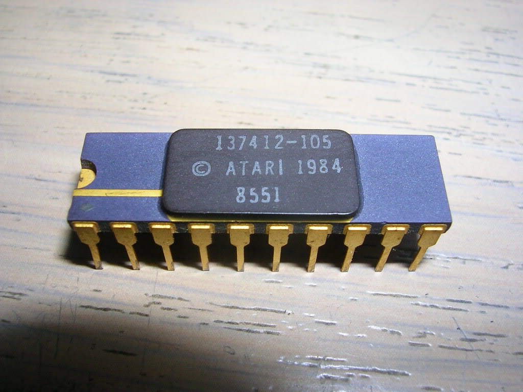
... and the problem was obvious.
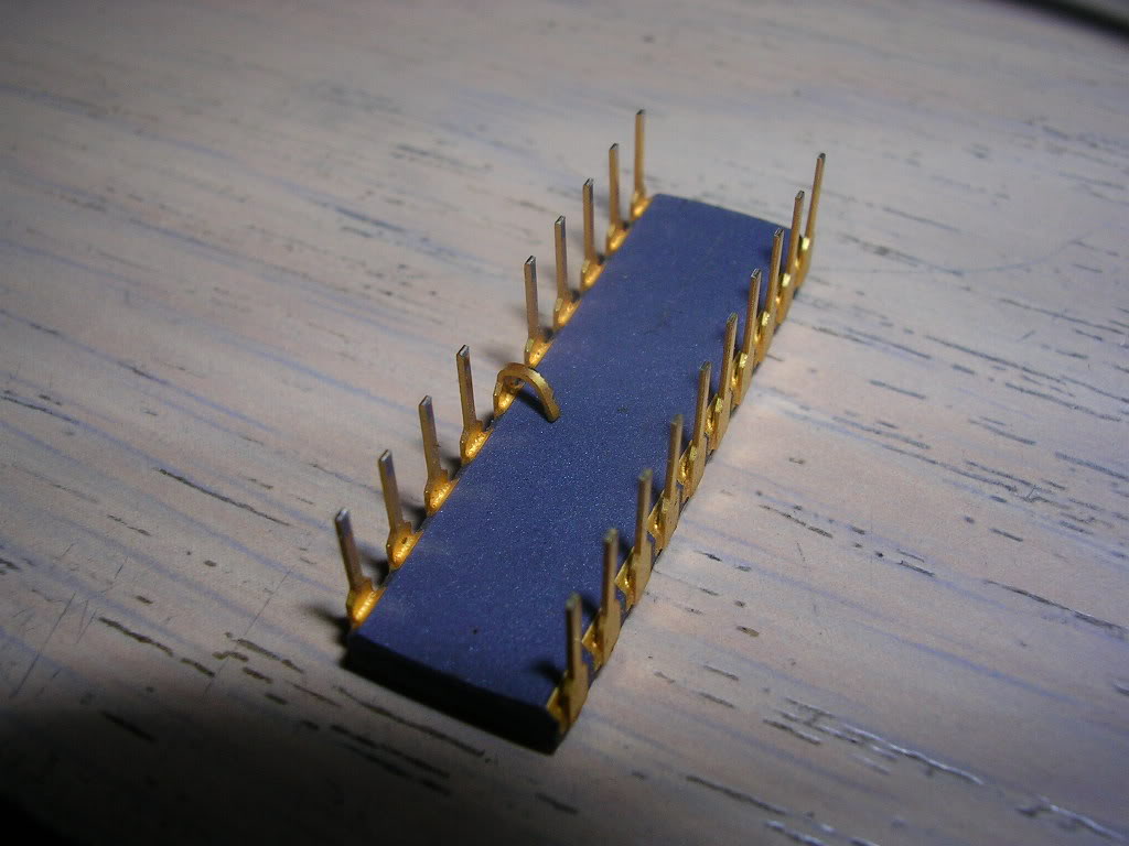
Once the wayward pin was straighted out with some flat bladed pliers and reinstalled she booted right up.
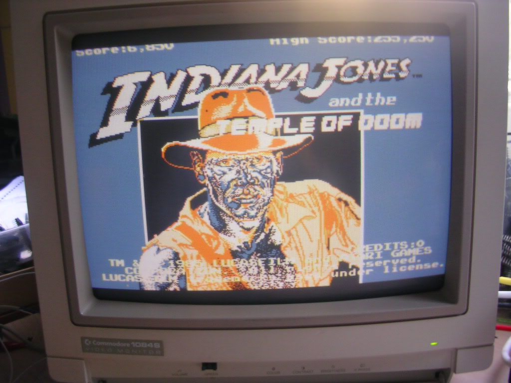
The splash screen was a bit of a mess but the game did run and was actually playable. No sign of the crashes reported by the seller.
The seller had said he thought he put a ROM back in the wrong socket on the back board and that turned out to be all that was wrong. the chip 136036-145 was in the wrong socket...
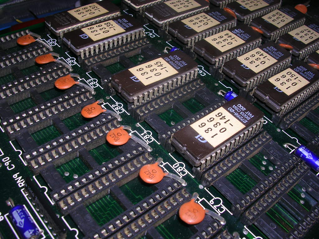
...it should be one to the left, next to the 136036-146 ROM.
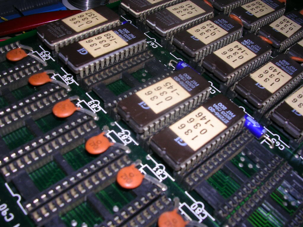
This was a bit of a guess on my behalf but it made more sense as 8bit ROMs often work as a pair on 16 bit system, so I took the punt and moved it.
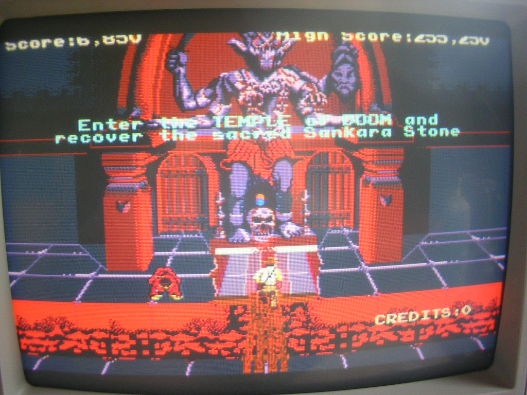
Once it was back in its correct location the splash screen was healthy again.
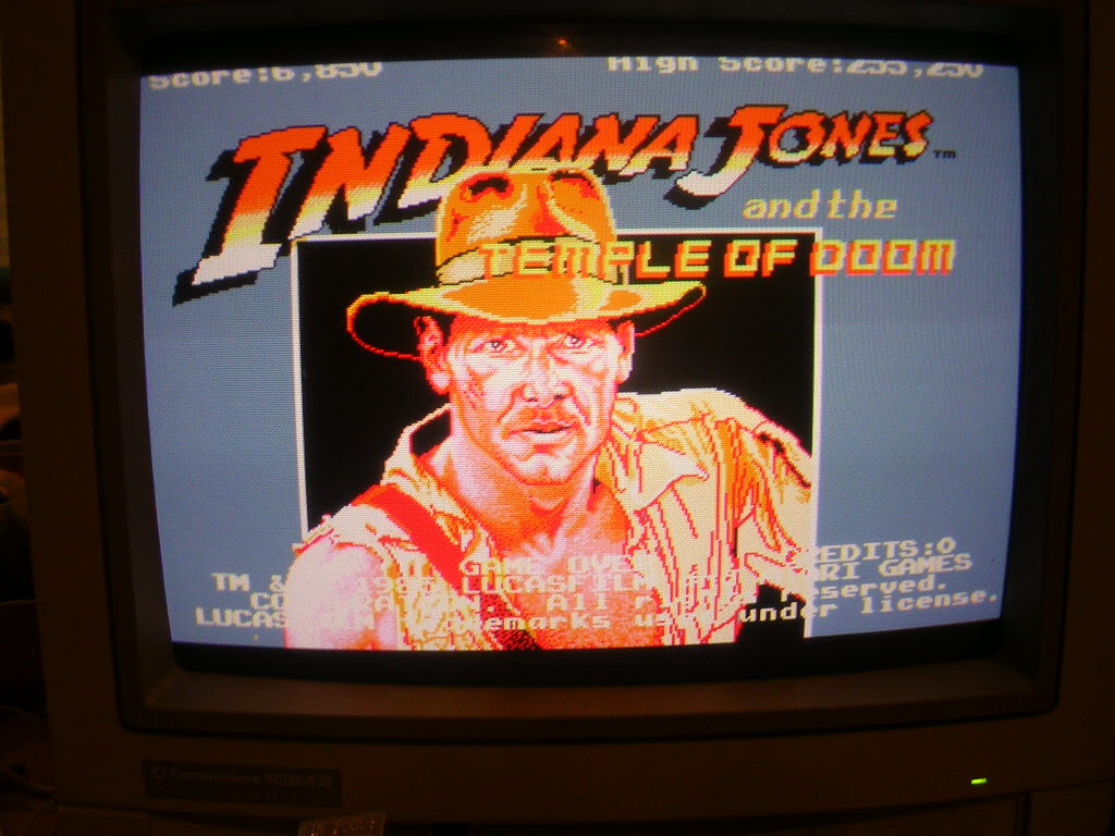
That seemed to be it, the game was playable and stable, for a couple of days anyway. At which point the original fault described by the seller returned. The game would report "Rom at 030000 error L" at boot, but would progress to the splash screen.
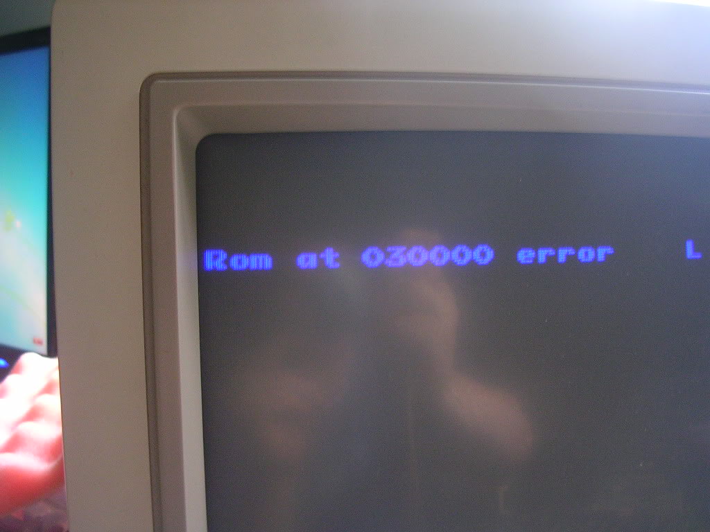
At the point that attract mode should run the demo, the board would crash, give the same message and restart.
Pulling up the MAME driver file "atarisys1.c" and based on the combination of ROM labels I worked out that this board was running the "indytempc" version of the game. As the game was crashing rather than giving corrupt gfx I focused on the maincpu section of the address space.

The ROMs 136036.568 and 136036.569 are the high and low ROMs that are located at the start address of 030000 on this board.
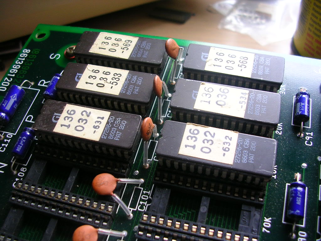
So I took them off the board to read them, the data dumps came back fine and once they were put back in their sockets the board booted and ran without the fault. Until I touched that area of the board again, at which point it crashed, gave the old error message and rebooted.
There was no sign of any dry joints, track damage or other abuse so the only thing left was a bad connection between the chip and the socket. The legs were dulled with oxide, but no more than any others, but I polished them back to a shine, used my chip pin reforming tool to straighten the chips and put them back in their sockets.
