PCB Repair Logs Rastan Saga
Rastan Saga
 |
|
| Manufacturer | Taito |
|---|---|
| Year | 1987 |
| PCB Image | Reserved |
| Pin Out | Jamma |
Repairer: Womble
Forum Thread: Rastan Saga PCB Repair
Board 1
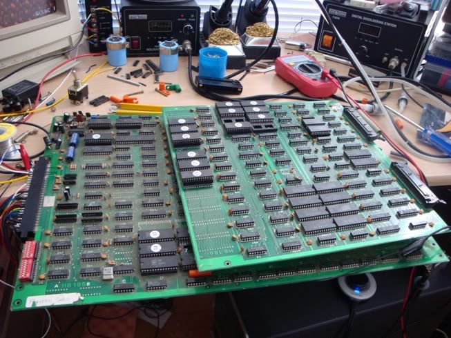
Offered to take a look at a Rastan Saga board that Mickaz had picked up on ebay as faulty, was sold as having graphics issues.
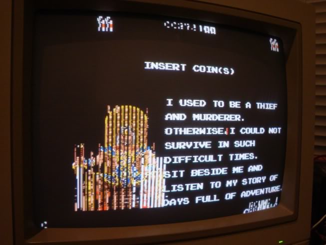
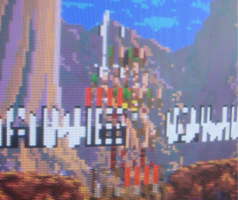
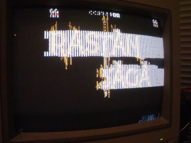
The game would run but the intro screens were a mess and the sprites were all mangled, the sound was also weak and rather raspy.
Thats the main character!
Turns out its a bootleg which can be both good and bad, good that there are likely to be few customs on it, bad that info on them can be scarce, MAME often doesnt have bootleg versions of games as the incentive to get yet another version of the game going is low once the original version is perfectly emulated.
In the case of this board it was a bad thing, I started of probing around and quickly found my way to PROM A18 on the top board, interupting the outputs on this chip made the messy stripes in the main sprites slightly less messy, still wrong but a more neater kind of wrong.
Pulling this chip out confirmed I was on the right track, the lack of data for those stripes makes them drawn as complete striped blocks.
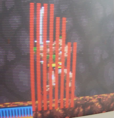
Its clear that the data for the sprites are contained within a pair of PROMs on this board. Pulling out the one next to it at A22 made the game display sprites as just blocks of red, ie the strips of good gfx data are missing and replaced with red stripes too.
So I went to dump A18 and my eprom reader detected out of spec pins, so I went looking in the MAME romset for the data - trouble was the MAME set is not the bootleg and the rom layout is very different to this board. The main game has fewer ROMs but larger capacity ones, and at different board locations.
So I dumped all 28 roms from the board and fired up a hex editor to see what was what. Took a while to find a match but eventually I found that $00000 to $08000 of the non bootleg version Rastan chip ic14_07.bin 1st was A20.bin from this board.
I figured that all the gfx data would be held in a bank of roms on the original board so I tracked down a decent photo of the original board and found that IC14, IC15, IC27, IC28, IC39, IC40, IC66 and IC67 are PROMs. PROMs and or mask ROMs are usually used for data that isnt going to change, ie sound and graphics data. The program code is often held on EPROMs which are more expensive but allow any bugs to be fixed at a later date. Working through these 8 ROMs I worked out that....
From Rastan Set
ic14_07.bin 0x00000-0x08000 is A20.bin
ic14-07.bin 0x08000-0x10000 is A26.bin
ic14-07.bin 0x10000-0x18000 is A19.bin
ic14-07.bin 0x18000-0x20000 is empty
ic15_05.bin 0x00000-0x08000 is A22.bin
ic15-05.bin 0x08000-0x10000 is A28.bin
ic15-05.bin 0x10000-0x18000 is A21.bin
ic15-05.bin 0x18000-0x20000 is A27.bin
ic27_08.bin 0x00000-0x08000 is A16.bin
ic27_08.bin 0x08000-0x10000 is A23.bin
ic27_08.bin 0x10000-0x18000 is A15.bin
ic27_08.bin 0x18000-0x20000 is empty
ic28-06.bin 0x08000-0x10000 is A25.bin
ic15-05.bin 0x10000-0x18000 is unknown
ic15-05.bin 0x18000-0x20000 is unknown
ic66_04.bin 0x00000-0x08000 is unknown
ic66_04.bin 0x08000-0x10000 is A4.bin
ic66_04.bin 0x10000-0x18000 is empty
ic66_04.bin 0x18000-0x20000 is empty
ic66_04.bin 0x00000-0x08000 is A5.bin with mods at start
ic66_04.bin 0x18000-0x20000 is A3.bin
From Rastan Saga set
rs07-37.bin is A12
rs09_43.bin is A14 very minor mods
rs21_42.bin is A11 very minor mods
ic76_20.bin is A1
This suggested that A18 was likely to be in ic28-06.bin either at 0x0000-0x8000 or after 0x10000 somewhere, so I wrote the 1st option to a new eprom, dropped it in and got all the sprites back.
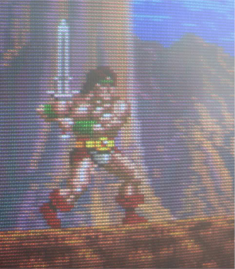
So - ic28-06.bin 0x00000-0x08000 is A18
The chip at A7 tested as being flaky when I was dumping the ROMs, it showed up as having faulty data lines so I was pretty sure this was the causing some of the problems. It would be fairly easy to find where the A7 data is in the mame set if I had the contents, in which case I wouldnt need to go looking anyway - all I had was a load of rubbish data from a duff PROM to go on, and no clues as to where it might be anyway.
I had already put a plea out for anyone with the same board who could dump some ROMS, SectionZ replied and confirmed that A7 contained the same data as IC39_03.BIN, so I burnt a new rom and that fixed the mashed title screen and intro.
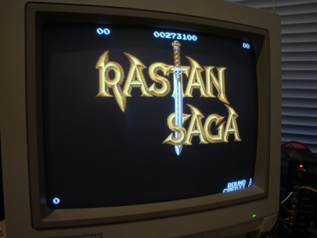
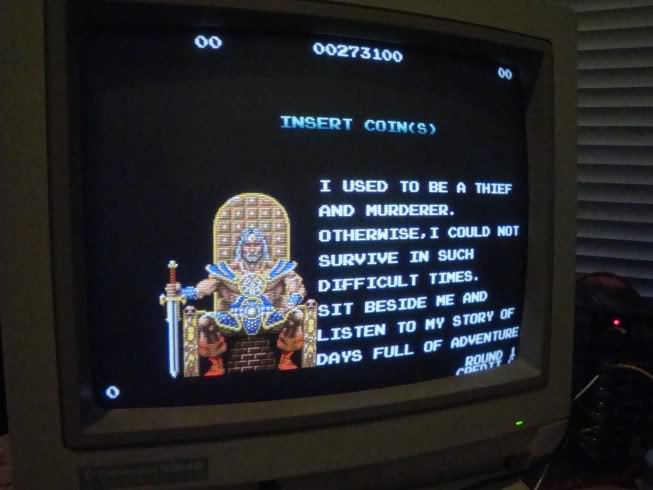
Next issue was the sound - very weak, volume pot didnt do much to it, and the sound was raspy. I had noticed initially there was a cap that had been wrenched to one side, dragging its guts out.
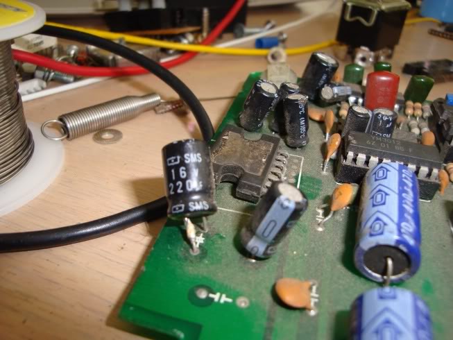
The amp chip has been fitted with the labelled side downwards, and the legs looked fragile, as did the solder side of the board so I didnt want to bend it up, or desolder iut. So I couldnt find out what that cap is for, but it connects to the amp chip, anyway replacing the cap fixed the sound fault. Ran ESR tests on all other electrolytics on the board and they are all fine.
The only remaining oddities are sparkles in the text when the game is booted from cold, they fade away pretty quickly and I am now fairly convinced they are caused by a bank of PAL chips on the lower board. If I crash the game there is about a 3 second wait before the watchdog notices and resets the CPU, during this time there are no sparkles, if they were due to faulty RAM they would continue as long as the bad area was being addressed. The likelyhood of fixing this issue is slim, PALs tend to be security locked, even if I had a working board here it is highly unlikely I could get the data off the good ones to replace these. They get damn hot (normal for PALs) and hitting them with freezer spray makes the sparkles increase. After the game has been running for 2-3 mins they are pretty low level and not that noticeable.
The other oddity is that this game is perfect at 4.7-4.8V measured on the board by the JAMMA connector, voltage drop to the furthest reaches is only 0.1V, but increasing the voltage to 5V makes the foreground elements flash on and off randomly, ie all sprites, icons and text. Returning it to 4.7V makes all these issues go away, I cant find anything obviously wrong to be honest - I suppose it is possible that this is just one of those very fussy boards, odd that it likes the volts lower than normal though!
Oh and I also soldered the volume pot in properly, from new it was leaning at about a 45 degree angle, one pin was barely touching the soldered pad - bloody bootlegs, assembled by drunk chimpanzees
Thanks again for your help SectionZ!
Repairer: Womble
Forum Thread: Rastan Saga PCB Repair
Board 2
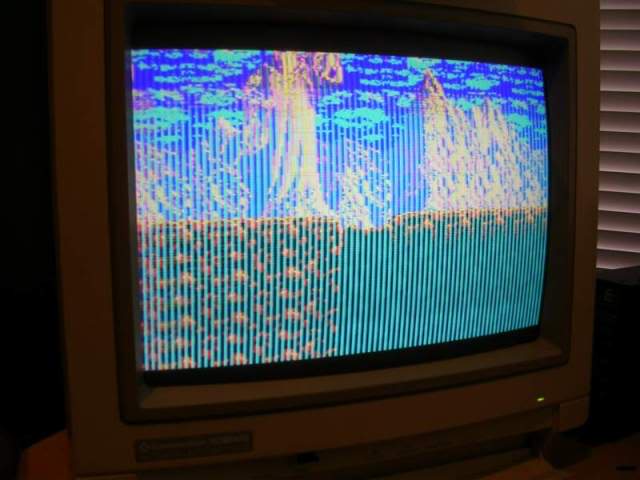
Got this one in a large batch of boards recently, looked in very good nick, and the game booted and ran but the graphics were pretty messed up. The screen had crazy colours and vertical lines through everything.
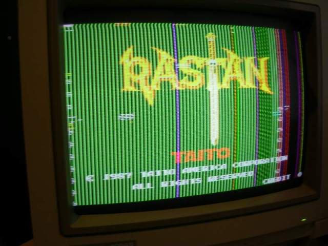
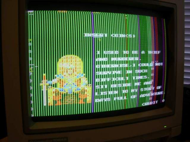
All in game sprites were missing too!
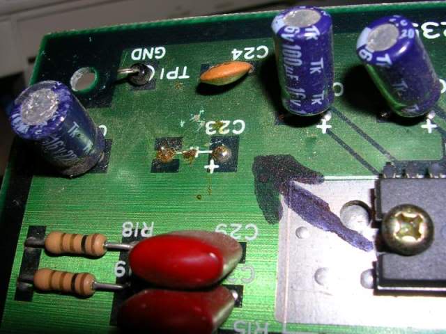
First thing to do is a visual inspection, looking for any damage, the board looked pretty mint, no gouges or scratched tracks, but a cap was missing from the amp section, which someone had labelled with a black arrow in texter...
..and someone had removed and replaced a couple of TMM2018 SRAM chips from a bank of 4, IC2 and IC3 were still soldered on the board, whereas IC4 and IC5 not..
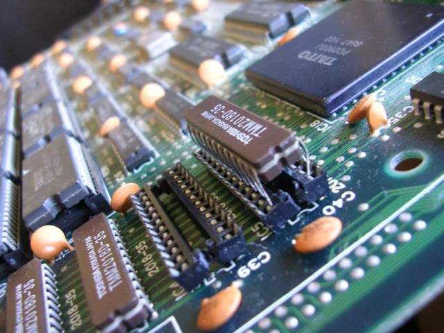
..they had been desolded, and fitted into sockets made out of cut up parts of other sockets. Pretty messy, and sadly whoever did this didn't use a chip to get the spacing right so the halves were wonky and the chip legs had to go down the outside of the contact pad bending the socket fragments and the chip legs at the same time.
Also on removing the two chips from their makeshift sockets it was obvious that one had lost half its ground pin...
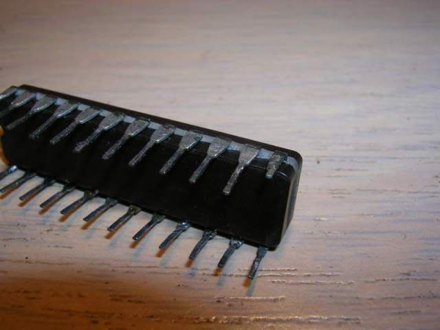
...presumably because 5V and ground pins are often hard to desolder due to the amount of copper attached to them wicking the heat away so quickly the solder never fully melts.
The remains of the leg were just long enough to look like it was a normal leg in the socket, but not long enough to actually make contact.
On removal of the half sockets them more damage was evident...
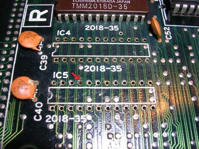
....pin 21 on the lower chip had ripped the plate through hole out of the board, breaking the connection to that pin. The pin is actually the WE (write enable) pin which allows the board to tell the chip to go into write mode, as opposed to read mode, without this pin the CPU can never actually store data in the chip.
A quick buzz round with the continuity beeper confirmed that this was the only borked pad so I fitted a couple of sockets. As there was no plate through hole to solder pin 21 to I fitted a wire link to the nearby via where the original track had run.
Fixing the leg on the 2018 chip was simple too, I trimmed the thin end of the broken leg, put the chip into a machined pin socket and inserted a pin cut from a faulty chip in my bin into the socket hole. One this was lined up properly and pushed into the socket firmly I soldered it to the tag left on the original leg. On removal from the socket it is actually hard to tell its been patched up. As the chip was now usable I could test it with its pair in my EPROM reader and both chips passed the test.
So I put them back on the board..
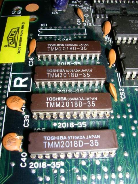
..and powered it up, everything was perfect again, the graphics artifacts were gone and all sprites were back.
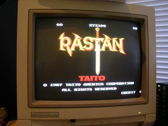
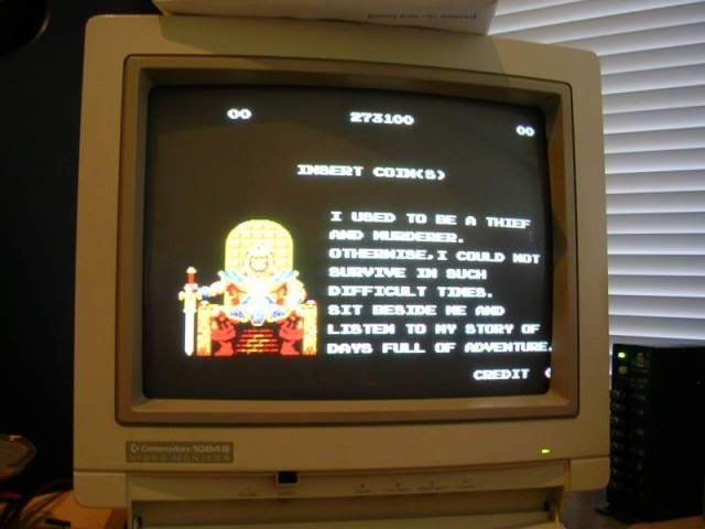
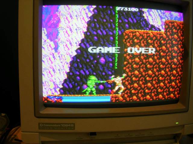
At this stage the game was working fine, the sound was good too, but the missing cap was included in the design for a reason, its there, along with a 0.1uF polyester cap to filter power supply hum on the 12V rail, so it needs to be there.
I tracked down the schematics and confirmed what the missing cap should be, a 1000uF 16V, and I had a spare from a scraped TV board. I removed the remains of the original cap legs, cleaned the black texter arrow off the board with some acetone and fitted the "new" cap in place...
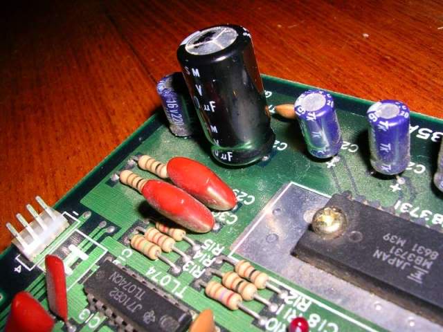
...it looks like the cap is bulging in this photo but its actually perfectly flat, just the flash I think.
The game has been running in my cab for over an hour now without any issues at all.
I did originally wonder why those two chips had been replaced as they looked like they were the original chips, as they were almost identical to the other pair in the bank of four. Also as the only fault was the damage done during their replacement it begged the question why they were replaced in the 1st place. But on closer inspection the batch number of the pair differ from the ones still on the board, so the original ones probably were the cause of the fault, the previous repairer just made things worse while tying to replace them and probably just gave up.
