PCB Repair Logs Rygar Bootleg
Rygar (Bootleg)
 |
|
| PCB Image | [http://wiki.aussiearcade.com.au/index.php/File:Pcb_rygar_bootleg.jpg |
|---|---|
| Pin Out | Reserved |
Board 1
Repairer: GameDude
Forum Thread: Rygar (Bootleg) PCB Repair
I had just received this in a box of PCB from another member so it was luck I guess (or fate??)
Anyway the PCB is not JAMMA so had to make a harness, powered it up and immediatly noticed one half of the screen had static garbage on the crosshatch screen but not the initail screen with tecmo on it and also in game half of the images were not displayed or were in the wrong spot (for sprites).
Hmmm thinking cap on.... OK its probably ram and on this board there are two layers the bottom being the video board so I went straight there.
A small note at this stage I should make is that upon inspection I did notice some blackened tracks indicating corrosion under some tracks from some form of liquid spilled on the video PCB side.
Anyway noted 2 x 6116 large ram on either side of the single row of ROMs a huge bank of 4064's (screen buffer??) and 1 x 2016 (probably sprite ram).
I figured out that the 2 x 6116 were responsible for loading the screen data and seeing as there were two and half the screen was muck and the other half was OK it seemed like a good place to start.
Checking with a probe showed everything was pulsing OK so decided to check the tracks where I had noted corrison before.... I dont fancy removing good ram for a lousy broken track and sure enough that was what it was.
Probing through about 20 odd traces revieled that one had a hairline crack.
I decided to make good all the tracks in one go so removed the PCB coating to reveal copper track, repair the trace that was broken and reseal with PCB laquer.
STATUS : FIXED
Board 2
Repairer: kane
Forum Thread: Rygar (Bootleg) PCB Repair
Have been Working on a Rygar bootleg board recently.
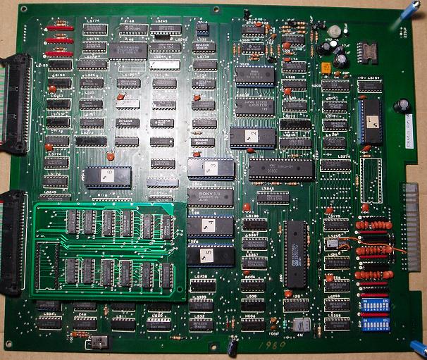
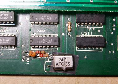
The board was in OK condition, some minor trace corrosion but not enough to be a problem, but was missing a 24 Mhz crystal and the main Z80 CPU on the main board. The original Tecmo Rygar boards use an oscillator unit, but this being a bootleg board, has a crystal with some extra circuitry instead. Intalled a Z80B and found a 24 MHz crystal on a scrap board and soldered it in.
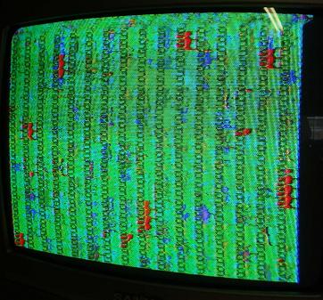
I pulled all the ROMs and they all checked out OK, so powered up the board and found a static screen of garbage.
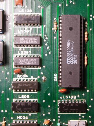
With the board not running, the first thing to do was to poke around the main CPU with the probe and check what signals were present, and pin 6 did not have a correct clock signal. Working backwards from the CPU the clock signal comes from a LS08 then via a LS139. Noticing that the LS139 was a Fujitsu brand IC, this was as far as I needed to go.
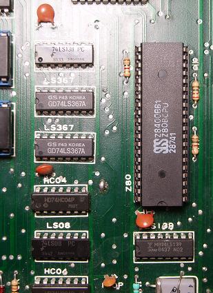
Piggybacked the 139 and the board ran and got straight through the RAM/ROM check and the game came up OK, so replaced the LS139.
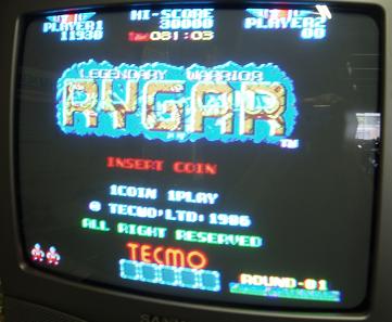
The game was now running fine but had a few minor issues. Sprite problems, background problems and sound problems.
The sound seemed to be playing OK, but was accompanied with a ton of scratchy static noise and would sometimes drop out to silence. Found a 220 uf cap near the amp that was loose, reflowing the solder on the legs stopped the sound from dropping out, presumably when the cap was bumped or moved.
The static noise pointed to a failing analog device, like a capacitor, DAC, or OP-AMP. Checking out the pair of IR3702 quad OP-AMPS (pin identical to a LM324), one of the outputs looked different to the others on the probe. A bit more experimentation and I could see a correlation between the varying static and the 3rd output at pin 8. I wouldn't have thought that piggybacking an OP-AMP would work but I tried it and it did mostly quiet down the static, so I desoldered the IR3702 fitted a socket and LM324 and the sound was good again.
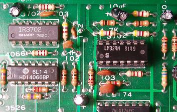
With that fixed the main board was all good and was now time to turn my attention to the video board and the issues with the sprites and backgrounds.
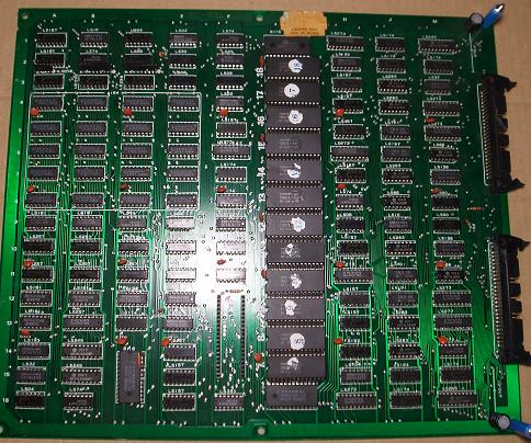
The sprites looked mostly good but half of them had what I'd describe as a fast golden coloured flicker, hard to explain and not possible to photograph unfortunately.
The backgounds looked as they should, but were all shifted up about three quarters of the screen height, so that you could just see the base of the background.
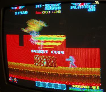
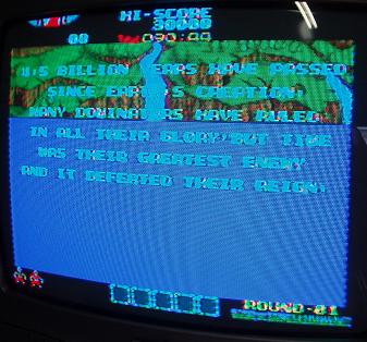
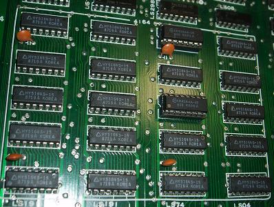
I first did a bit of reading in the MAME source code and some playing around with the Rygar MAME ROMs to figure out which ROMs did what. There are 12 GFX ROMs on the video board, arranged in three sets of 4 ROMs each for GFX2, GFX3 and GFX4. The top 4 are for backgrounds, the middle 4 are sprites and the bottom 4 are for static foreground graphics, each group with their own 6116 SRAM in addition to a bank of twenty 5164 64k X 1 DRAMs for the sprites.
The SRAMs all looked good so the most likely culprit for the sprite issues where the DRAMs. Actually I suspected the DRAM mostly because I had no replacements, usually the way it goes, and I was right too as I found two faulty DRAMs causing the flickering. I had another rygar video board here that had all the DRAM socketed so I could pull some of them to use on this board, although they were 4164s, so either that or 5164s will work. Replacing the one at location C4 cured the problems with the Dragons and the Powerups, and replacing C6 fixed the Crabs, Blue Monkeys and Powerup Containers.
Up to this point the problems had not been difficult to find, but the last problem with the mislocated backgrounds took me a long, long time to find.
The backgrounds being complete means the data was intact, but with the location being off pointed more to an addressing problem, but all the RAMs and ROMs looked good, so I had to follow the address lines all over the board and it took many hours before I found something arie. Some of the ROM address lines came via a pair of LS283s at J3 and J4 which should have matching signals at their respective pins, but one had 2 inputs wrong. Traced the inputs over to a pair of Fujitsu LS273s which are suppose to share a few signals but a connection was broken between pin 18 of each IC.
A closer inspection of pin 18 of the 273 at M5 showed a very small patch of corrosion that had seperated the base of the pin from the trace. There was no other corrosion like this anywhere else on the board, just one small spot
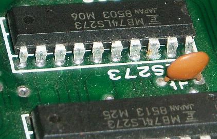
Joined pin 18 of each 273 with hookup wire under the board and the backgrounds returned to their rightful positions, board now 100%.