PCB Repair Logs Vindicators
Vindicators
 |
|
| Manufacturer | Atari |
|---|---|
| Year | 1988 |
| PCB Image | Reserved |
| Pin Out | Reserved |
Repairer: Womble
Forum Thread: Vindicators PCB Repair
My mega project at the moment is the Atari Vindicators cabinet I bought from ExtraBall, am a sucker for Atari cabinets, especially ones with unique controllers.
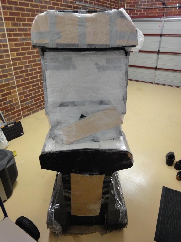
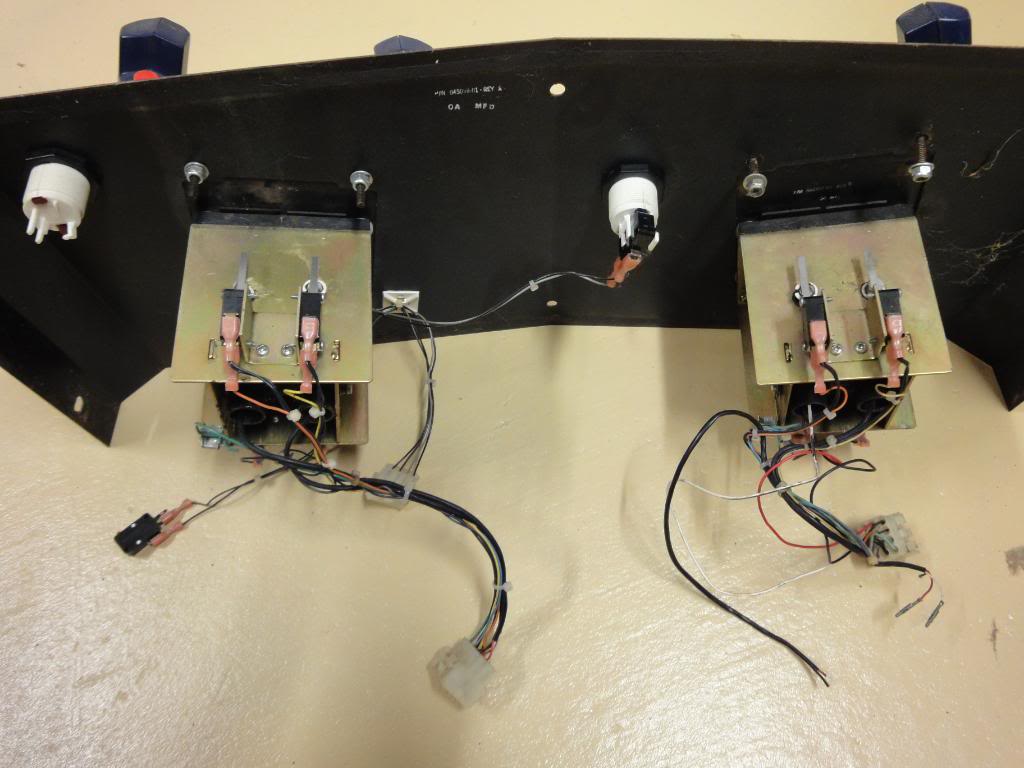
Well the woodwork is a bit of a mess, and the controllers are down for the count as the wiring is in a bit of a state...
...but after a quick scout round with the multimeter I was very pleased when I flicked the switch. The monitor image is beautiful and the game booted up.
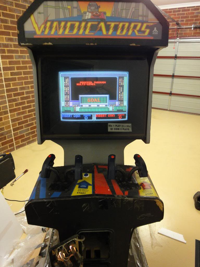
Initially I thought everything was good, the attract mode of Vindicators takes about a week to get round to the actual game and as the controllers were non functional all I could do was wait. When it finally got the game the sprites were not right, they were missing some of their coloured fill regions and the flicked about horizontally from where they should be according to the game itself, ie the turret would sometimes be 3cms to the left of the explosion when it was destroyed. The explosion was also missing all of its yellow,and some of the play field area was wrong, the bunkers were mashed up and the end of level doors were not correctly drawn.
There was also no sound at all, I wasn't that worried as I got the "bong" noise when I powered her up, and after some poking around, by flicking the coin mechs I could get the same sound again. I was after some "attract mode" sound so I flipped out the manuals that came with the cab (Operators Manual, Full Schematics and Monitor Manual - wooh nice) and found the switch for "service mode" on the audio PCB.
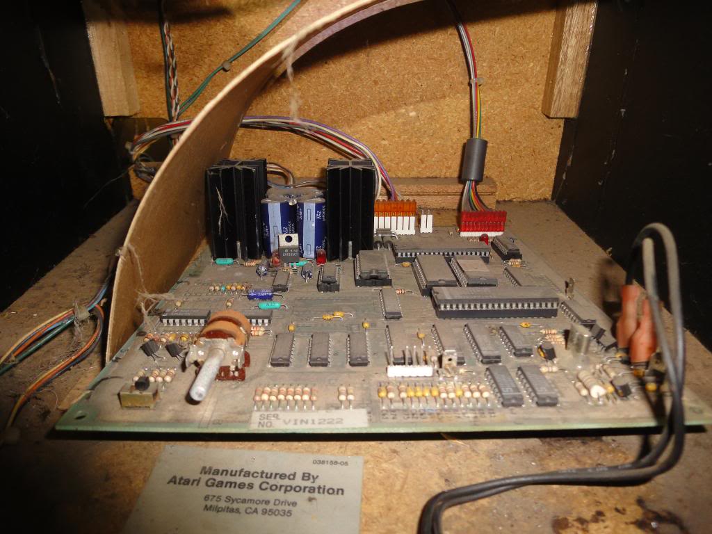
The setting for attract mode sound was already set to "yes", slightly worrying, but not as worrying as the complete lack of sound when I flipped back to normal mode. The game rebooted but now I had no sound at all, I also could no longer coin the game up. Assuming I had disturbed a dirty ribbon cable I went round all the connections and reseated them all, no change. Flicking back into test mode I went to the audio test section only to have it fail giving the message "Audio System Failure".
The was a pain in the arse for two reasons, firstly it was late and I hate trying to go to sleep having made something worse, it never works and I have stupid dreams about the fault all night, sad but true. Secondly there was no easy way to get this board set going on the bench, it is typical Atari and relies on sockets to the PCB to connect everything, not a JAMMA edge connector in sight. Also the audio PCB is rather well hidden with 4 connectors at the very back of the board, which you cant see when you have your hand in the cabinet. With no other option I had to get the PCB out of the cabinet, I stuck the digital camera into where it lives and fired off a few "pre" shots and then pulled all the cabling out releasing the board.
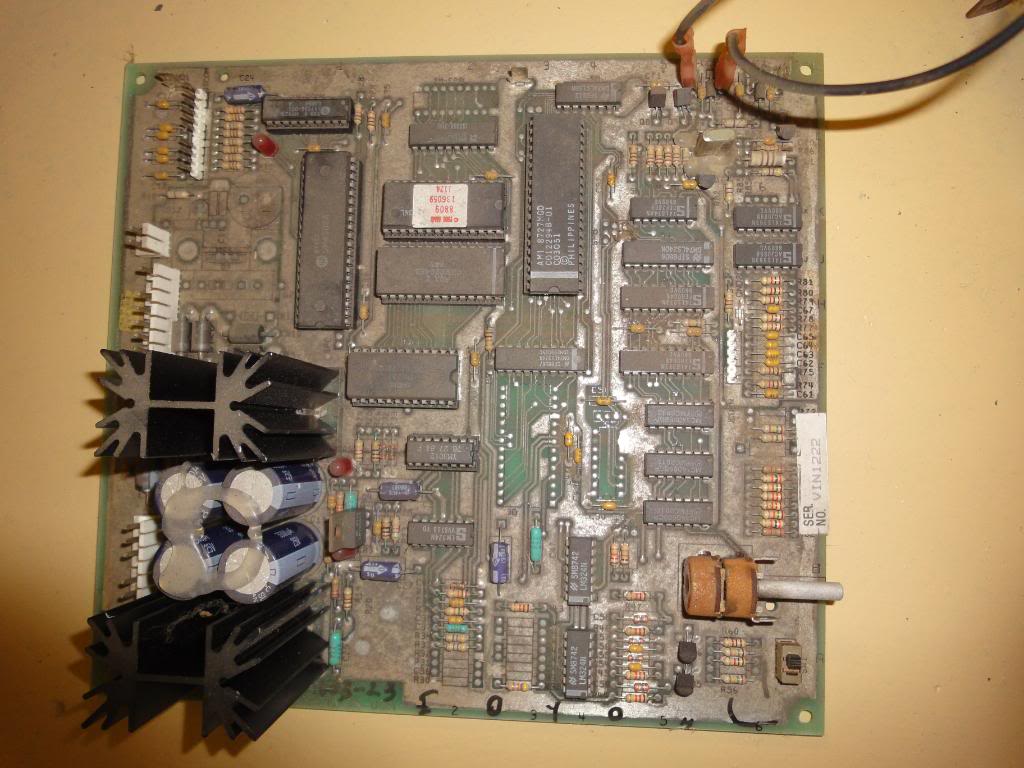
First thing that struck me was the bridge rectifier quad of diodes and two smoothing caps, bad news as if this puppy needed AC to work fully I was going to struggle to rig it up on the bench. The PSU section of the cab had been bodged together with an old AT PC PSU and was relying heavily on manky old gaffer tape as insulation.
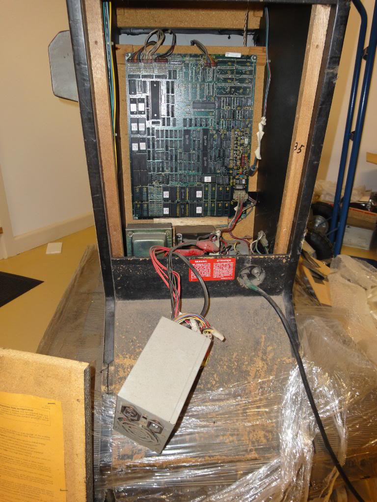
Moving the whole system to the bench safely was going to be a lot of work. Anyway - at least part of the PCB was normal TTL level logic, a 6502 CPU, a dose of RAM and ROM and some common TTLs. One great thing about Atari boards is that they were not afraid of using sockets, so everything bar the TTL was easily removed. The RAM and ROM passed their tests in my Wellon VP280, which left the CPU, as the coin mechs and coin counter all required 12V it makes sense that they are located on the same PCB as the amplifier chips which tend to required the same, at this stage I had no idea how the AC inputs were treated but it seemed logical that the CPU on the audio board would deal with the coin-ups as they were physically close to the 12V required by the rest of it, this wouldn't be the 1st board I have met where the sound CPU handles the house keeping as well. As the 6502 was socketed I replaced it with one from a scrap board, reassembled the cabinet and flicked the switch. Bong!! The sound was restored and I could once again coin-up the board, after all of this it turns out that the attract mode sound only kicks in once every ten minutes or so, and you have to wait ten minutes from the point you power up to hear anything. I had left the cab running for a while and heard it start to play its tune from afar, it scared the crap out of Mrs Womble as the volume was not set to "gentle".
With the sound issue fixed I took the main board out, no chance of easily powering it up but as all the RAM, ROM, CPU and custom chips were socketed there was the chance of some testing off board. The 27512 ROMs all passed..
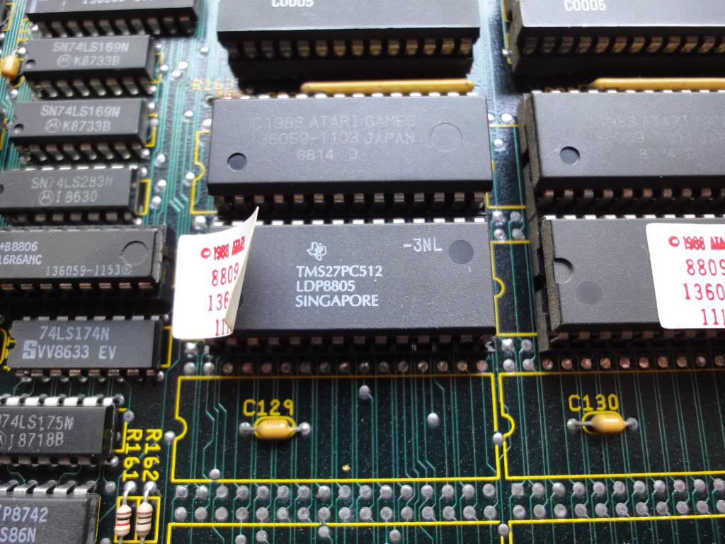
... as did the pair of 2018s and the four 6265 type chips with a virtually unknown-to-google chip ID. The CPU clearly was fine as the game ran, which left the customs and the PALs. As a repairer I loath PALs, they are programmable logic and contain a security feature, if the bloke who programmed it didn't want anyone to read out the contents again he could set a security bit meaning if you didn't already have the data you had no chance of making a new chip, you can erase the one you have but not extract the code again. As they are programmable logic they replaced lumps of normal TTL which you might have a chance of troubleshooting, they also tend to be highly game specific and the code may not exist anywhere. MAME doesn't use the contents of the PALs on many games although there is a project going on to backfill the DB with the correct PAL data. Plus plus plus my burner doesn't support the kind found on most boards of the era I work with, all in all we hates them.
So, the PALs I could do nothing with, which left the other Atari customs, if they were not in sockets I would probably not have focused on them so early but it was too good an option to rule out a whole lot of unknowns if I could swap in known good chips. I have an Atari Gauntlet board which has 3 of the 4 customs on it too, it works perfectly and its customs are also socketed.
But I decided that squatting down in the garage in the back of a cobwebby cabinet was not the way to go about swapping in highly unusual chips that if I killed I would struggle to replace, I had a bad Vindicators pcb, I did not want a bad Gauntlet PCB to go with it.
So I bit the bullet and made the harness. The schematics were a god send, they are available online but a paper copy is much easier to scan by eye looking for relevant bits. Obviously the main board was primarily powered by 5V, however it also got 14V from a tap on the main transformer, via the sound board, which went straight into a 3 pin voltage regulator on the mainboard, the output voltage of the regulator was determined by the support components around it, not by the chip itself. According to the schematics it should be 10V which goes into the video generation portion of the main board. The datasheet for the Vreg confirmed it would be happy with 12V input so that simplified that part of the system. The power supply for the audio board was also simpler than I thought, all the AC voltages are are rectified, smoothed and go off to the amplifier section and the coin mechs, neither of which I needed to power up on the bench. Also to Atari's credit they tend to pepper their boards with test point lugs so if you don't happen to have the correct sockets you can hook up power with some spade connectors with resorting to any forms of buggering around with the original sockets. All of this was soldered up to a JAMMA biscuit and a 9 way pin header allowed me to get the video out too. With the original PCB linker cable extracted from the cabinet I was able to power the board up on the bench without having to worry about the bodgy mains cabling (yet).
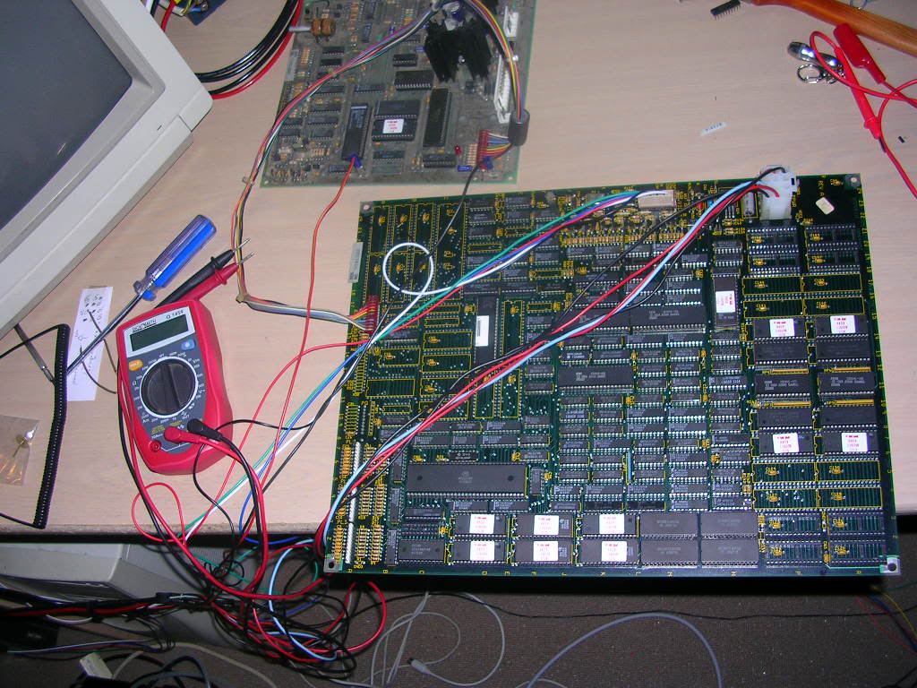
With it on the bench I could quickly swap in the known good 137418-101, 137419-103 and 137419-104 chips...
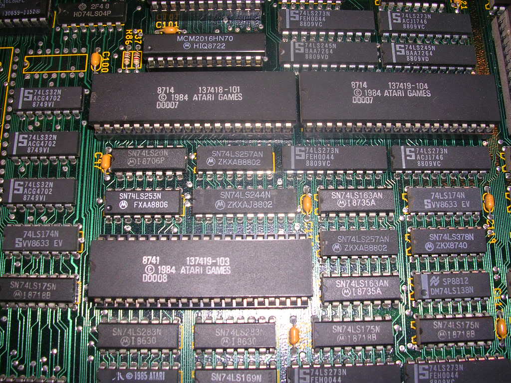
... from Gauntlet, which achieved nothing, the game ran as before with the same mangled sprites. This left the two fantastically named SLAGS (Syn Logic Array Graphics Shifter) chips and a 137536-001 chip. The SLAGS are sit on the bus that the gfx ROMs live on and removing one or the other blew lines through all the gfx, so it was not likely that they were involved in this fault as if they were partly faulty it should show up on all gfx relying on data from these EPROMS.
The 137536-001 (with the rather dull name "LB", Line Buffer?) ...
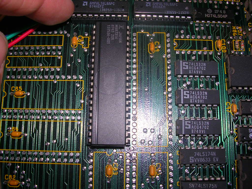
...isn't used on Gauntlet either and a search online showed it was used on a range of other board, none of which I have access too.
So it was scope time, having gone through the schematics I had noticed a set of lines call HPOS0-HPOS7 in what looked like the graphics subsection, Horizontal Position lines perhaps? So I focused on that part of the board, the "LB" takes the 8 HPOS lines as its address bus...
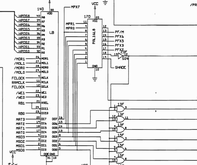
... from a pair of 74ls83 chips at 10K and 10J, their outputs seemed to be healthy enough when their inputs were active, but when there was silence the outputs did look a bit vague. The LB also takes an 8 bit data bus called MAT, I can only guess what it stands for, perhaps "match", basically I was looking for anything that looked like it was XOR'ing gfx data which is how sprites are overlaid on a background. The page all this was on was labelled "Mo Control", so assuming it has nothing to do with facial hair it sounded rather spritey.
The MAT and HPOS fed into the "LB" chip along with a few other lines, and as the whole sprites were jumping I was looking for areas dealing with 8 data lines at once rather than the odd bad line. With the LB chip off the board all the sprites vanished, further suggesting I was on the right path, either upstream, or downstream of the fault anyway, or perhaps right at it!. I went round the HPOS and MAT input lines with the scope when the board should have been moving sprites around and they looked fine, as did the clock and write enable lines going to LB. Unfortunately the attract mode of Vindicators takes ages to loop and includes only a couple of short scenes where there are actual sprites on the screen so it took a while to gain enough "sprite time" to check it all. Despite all the inputs the LB chip only has 8 outputs, another data bus, which goes to both a dreaded PAL and to a raft of OR gates across two LS32 chips. The "other" signal that the LS32's are ORing against is an output of the same PAL. With the board powered up and at the right point in the attract mode cycle I probed the 8 data line outputs from the LS chip, all looked good apart from pin 7 which is DO2. All the other pins were rapidly transitioning from logic high to logic low, pin 7 however was doing it a lot slower, it was still flipping but it didn't seem to match what the others were doing. Its a bit of a leap of logic to assume its bad based on what you see on a non-storage o'scope as you only get to see a very small timeslice, if it had been the high line on an address bus it would have been less of a worry but as a "middle of a byte" data line it looked suspicious. By temporarily shorting DO1 to DO2 I could annoy the fault, the sprites would flick along the horizontal plane and some of the missing colours would reappear, totally wrong colours but the sprites were briefly getting coloured in.
At this point I could go no further, I had 3 suspects, the two 74LS83s feeding the LS chip, and the LS chip itself. As I really prefer to leave a board as untouched as possible I was faced with finding another LS chip or bite the bullet and desolder the LS83s.
A day or two passed and I was still trying to track down a 137536-001, andysarcade.com sells them but are out of stock, so I was working further and further back through the google search results, until I found a badly parsed pdf manual of Atari's KLAX, a game I had sitting on the shelf in the spare room. I had thought that KLAX was circa 1991 or 1992, the attract mode states that it is now "the nineties and time to play KLAX", and as you only tend to find customs on games of the same era within any manufacturer I had not bothered to look. Not one of the earlier sites mentioned that the chip was used on KLAX, I pulled in the full manual and yep, it has a 137536-001 on board. It is actually from 1989, at the most its only 2 years younger than Vindicators, in reality it is probably less than 2 years. A quick trip to the spare room, found the board, pulled the 137536-001 out of its socket, installed it into Vindicators and powered up. One small eternity of waiting for it to demo of the game later..
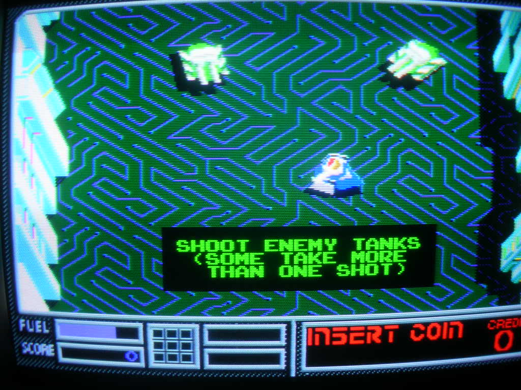
..fixed, the sprites were where they should be...
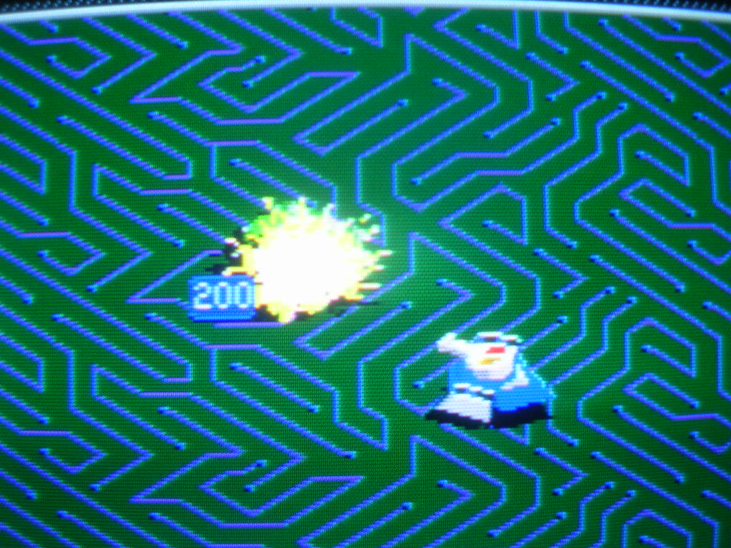
...and all the component parts of the sprite were aligned...
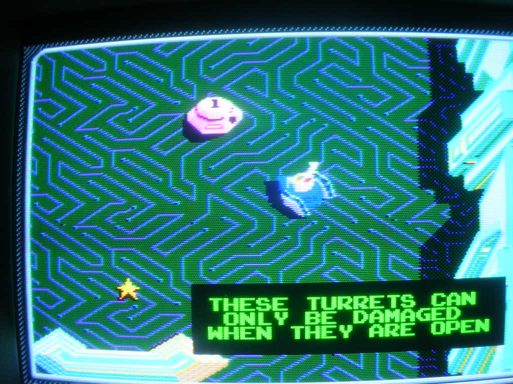
...the turrets looked like turrets again
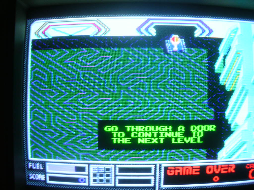
...and the end of level doors were correct again.
Had I known I had a 137536-001 on KLAX earlier I could have ruled this out without the several hours worth of work but in a way I am pleased that I had narrowed it down to within 3 chips, unfortunately it turned out to be the least easy one to replace. KLAX can live without its LB chip until I find one so its no great hardship. Just for kicks I put the bad LB into KLAX to see the result, rather unsurprising it was much the same fault. The sprites of the blocks coming down the conveyor were missing their colour fill, and were often off to the side of the conveyor to such a degree it was impossible to play the game.
Next step is to rewire one of the controllers so I can at least have a game, then its time to work on the cab itself, a fair bit of woodwork and a tray of metal bits for the local powder coaters.
Much work to be done!